A rod-guided composite spring damper

A composite spring and damper technology, used in springs/shock absorbers, springs, coil springs, etc., can solve the problems of reducing the cost of shock absorption, waste of resources, inability to stretch and consume energy and reduce vibration, and reduce the cost of shock isolation. , the effect of shortening the length

Active Publication Date: 2018-07-10
徐州天泓传动设备有限公司
View PDF6 Cites 0 Cited by
  • Summary
  • Abstract
  • Description
  • Claims
  • Application Information

AI Technical Summary

Problems solved by technology

However, this utility model patent obviously has the following disadvantages: 1. Two coil springs are required, and the length of the entire damper is relatively long, which is not suitable for installation in a space with a small distance; 2. It is difficult or even impossible to ensure the two springs in the process Only the stiffness of the spring (including tensile stiffness and compression stiffness) is equal, so the shock absorption effect is different in different wind directions; 3. The initial stiffness of the damper cannot be changed to achieve the preset wind resistance level and reduce the cost of shock absorption; 4. A helical spring works in two states of tension and compression at the same time. The metal material and production process of the existing spring are difficult to meet the requirements. The two working states of tension and compression can only be realized by reducing the elastic deformation range of the helical spring. , which obviously wastes resources
The above three means of changing the effective working length of the spring are obviously not suitable for composite springs; in addition, this type of anti-shock absorber not only shortens the effective working length of the spring, but also can only compress energy and reduce vibration, and cannot stretch energy. Vibration reduction

Method used


Image

  • A rod-guided composite spring damper
  • A rod-guided composite spring damper
  • A rod-guided composite spring damper

Examples


example 1

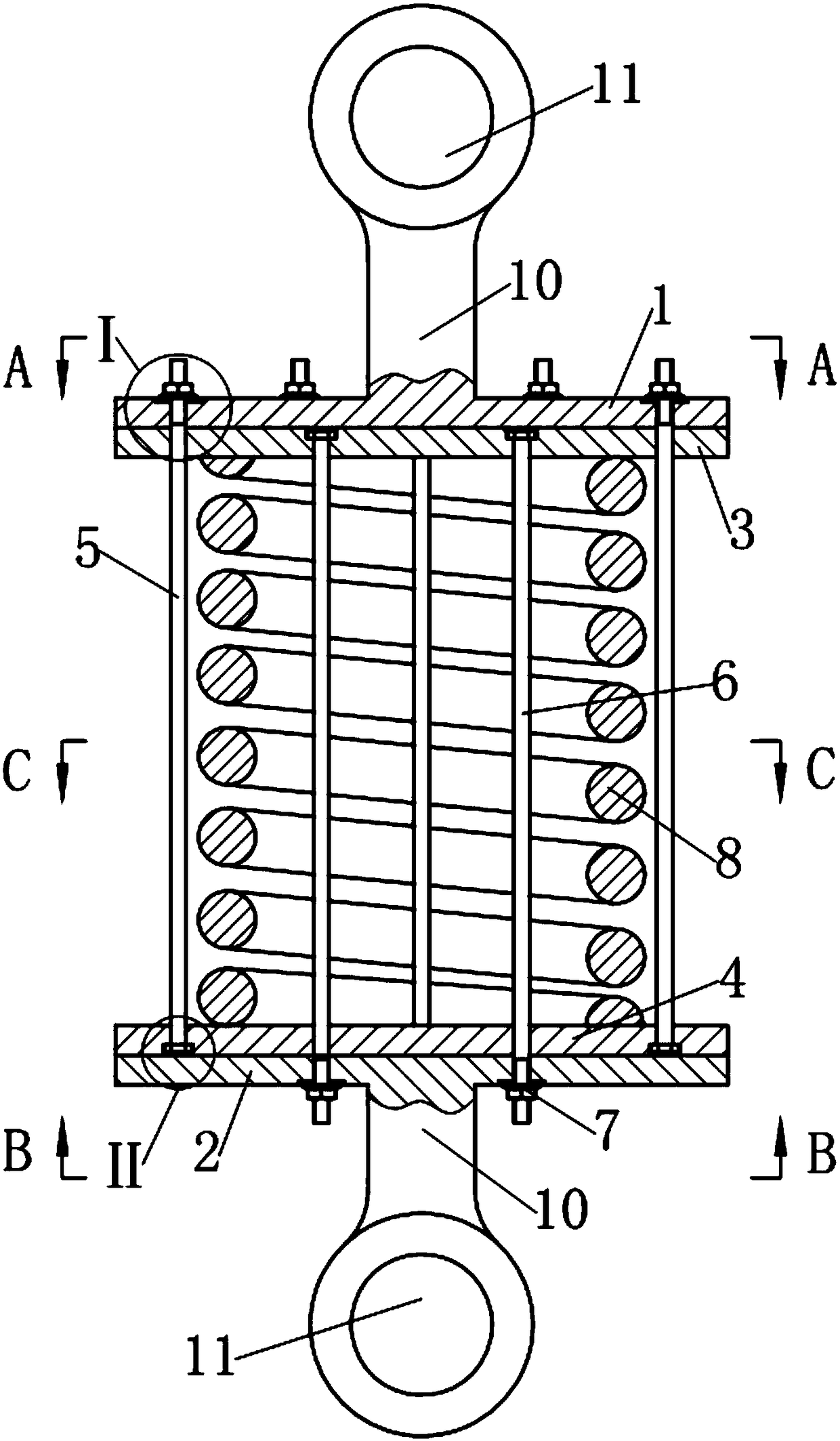
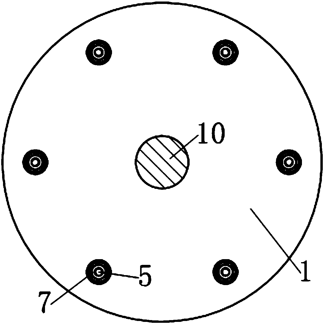
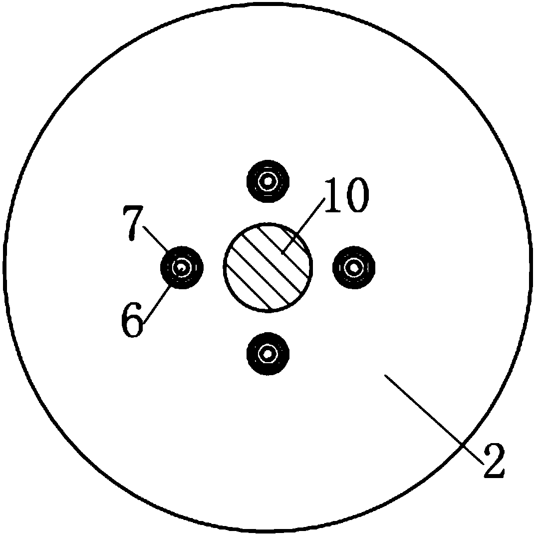
[0025] see figure 1 , The rod-guided composite spring damper in this example is an energy dissipation device that can be used for seismic reinforcement of building structures. The two end plates are the upper end plate 1 and the lower end plate 2 located at the upper and lower ends of the composite spring 8 respectively. The upper surface of the upper end plate 1 and the lower surface of the lower end plate 2 respectively extend a connecting rod 10 along the axis of the composite spring 8 away from the composite spring 8 . The end of each connecting rod 10 is provided with a hinge hole 11 .

[0026] see Figures 1 to 6 , the back pressure device includes two sets of polished rod bolts as pre-pressing rods, two floating pressure plates and ten hexagonal flange nuts 7 as limiting elements; wherein, the two floating pressure plates are respectively arranged on the upper end The first floating pressure plate 3 between the plate 1 and the composite spring 8 and the second floatin...

example 2

[0035] see Figures 7 to 10 , the rod-guided compound spring damper in this example is a vibration isolation device (also called isolation bearing) that can be used for vertical isolation of buildings. Compared with Example 1, this example has the following differences:

[0036] 1. As a shock isolation bearing, in order to facilitate installation, the connecting rods set on the two end plates in Example 1 are omitted in this example, and the upper end plate 1 is extended axially upward from the edge and then radially outward. And connecting bolt holes 12 are evenly arranged at the edge; the lower end plate 2 is extended axially downward and radially outward from the edge, and connecting bolt holes 12 are evenly arranged at the edge; wherein the upper surface of the upper end plate 1 A gap larger than the amplitude of the composite spring 8 is respectively set between the upper end of the first group of polished rod bolts 5 and the lower surface of the lower end plate 2 and the...


PUM


Abstract

The invention discloses a pull rod guide type complex spring damper. The pull rod guide type complex spring damper comprises two end plates, and a complex spring is arranged between the two end plates. The pull rod guide type complex spring damper is characterized in that a back pressure device is further arranged between the two end plates, the back pressure device comprises two groups of prepressing pull rods and two floating press plates, one press plate is arranged between one end plate and the complex spring, and the other press plate is arranged between the other end plate and the complex spring; the two groups of prepressing pull rods are parallel to the axis of the complex spring respectively, one group of prepressing pull rods are symmetrically distributed in the center hole of the complex spring around the axis of the complex spring, and the other group of prepressing pull rods are symmetrically distributed at the periphery of the complex spring around the axis of the complex spring; and one ends of each group of prepressing pull rods are fixed to one floating press plate respectively, and the other ends of each group of prepressing pull rods penetrate through the other floating press plate respectively and are fixed to a limiting element together with the end plate adjacent to the other floating press plate.

Description

technical field [0001] The present invention relates to a damping device, in particular to a damper using a compound spring. Background technique [0002] The composite spring is called the rubber metal spiral composite spring, which is a kind of spring formed by wrapping a layer of rubber material around the metal spiral spring. The composite spring has the nonlinear characteristics of the rubber spring, and also has the characteristics of large deformation and large bearing capacity of the metal coil spring, and its stability and bearing capacity are better than those of the rubber spring. Because the composite spring has a working characteristic curve similar to the rubber air spring, but has a simpler structure than the rubber air spring and has no risk of gas leakage, it is also used to replace the rubber air spring and is widely used in mining, metallurgy, coal and other large-scale vibration equipment. Vibration reduction and building isolation. [0003] A single me...

Claims


Application Information

Patent Timeline
Patent Type & Authority Patents(China)
IPC IPC(8): F16F7/00F16F1/06F16F1/12E04B1/98
CPCE04B1/98F16F1/06F16F1/123F16F7/00
Inventor 沈珊胡济福胡济全
Owner 徐州天泓传动设备有限公司
Why Eureka
Try Eureka