LED lamp cooling structure

A technology of LED lamps and heat dissipation structure, which is applied in the direction of cooling/heating devices of lighting devices, lighting and heating equipment, and parts of lighting devices, etc. Ideal and other issues to achieve the effect of ensuring long-term normal work, improving production efficiency, and rational and novel design

Pending Publication Date: 2017-02-22
夏孔能
View PDF6 Cites 1 Cited by
  • Summary
  • Abstract
  • Description
  • Claims
  • Application Information

AI Technical Summary

Problems solved by technology

For the heat dissipation problem of LED lamps, there are various heat dissipation structures on the market. Generally, the substrate is set on a heat sink made of heat-conducting metal to increase the heat dissipation area and improve the heat dissipation effect. The design of most heat dissipation structures is cumbersome and complicated, which affects mass production. High efficiency, high manufacturing cost, not fast enough heat transfer, unsatisfactory heat dissipation effect

Method used


Image

  • LED lamp cooling structure
  • LED lamp cooling structure
  • LED lamp cooling structure

Examples


Embodiment Construction

[0018] It should be understood that the specific embodiments described here are only used to explain the present invention, not to limit the present invention.

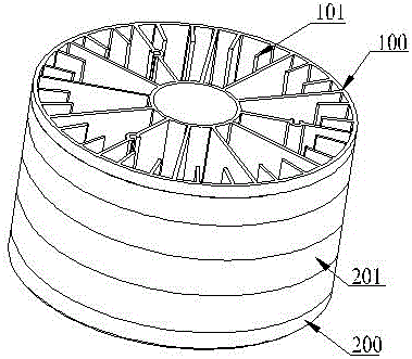
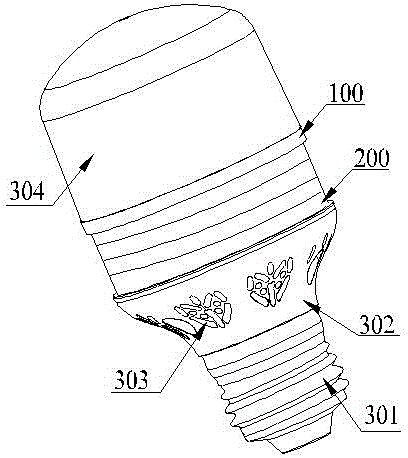
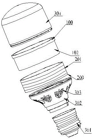
[0019] refer to Figure 1 to Figure 3 , an embodiment of the heat dissipation structure of the LED lamp of the present invention is proposed. The LED lamp includes a substrate with a number of LED lamp beads uniformly arranged on the upper end surface. The heat dissipation structure can be installed on the LED lamp. The LED lamp of the present invention can be a light bulb, a light projection Lamps, high bay lights, downlights, spotlights, ceiling lights, track lights, etc., the heat dissipation structure can be installed on various LED lamps, and has a wide range of applications.

[0020] The heat dissipation structure is closely attached to the lower end surface of the substrate, and includes a hollow heat sink 100, and a heat dissipation silica gel layer 200 with heat conduction effect that is arranged on the outer...


PUM


Abstract

The invention discloses an LED lamp cooling structure. An LED lamp includes a substrate uniformly provided with multiple LED beads on the upper end surface; the cooling structure can be mounted on the LED lamp, and is tightly bonded and fixed on the lower end surface of the substrate; the cooling structure includes a radiator with a hollow internal, and a cooling silica gel layer tightly butted against the outer side wall of the radiator and having a heat conducting effect; multiple cooling ribs are arranged on the outer side wall of the cooling silica gel layer; the cooling ribs and the cooling silica gel layer are set as an integral forming structure, and are manufactured by a heat conducting composite material; multiple cooling fins are uniformly distributed on the inner side wall of the radiator; and the cooling fins and the radiator are set as an integral forming structure, and are manufactured by heat conducting metal. In the cooling structure, the cooling silica gel layer with good cooling performance is encircled around the outer side wall of the radiator with good heat conducting effect for dissipating heat conducted during working of the LED beads into external air by the quickest speed to achieve the ideal cooling effect; and the LED lamp cooling structure is simple in structure, reasonable in design, ideal in cooling effect and low in manufacturing cost.

Description

technical field [0001] The invention relates to the technical field of LED lamps, in particular to a heat dissipation structure of LED lamps. Background technique [0002] LED has been widely used in various lamps because of its advantages of energy saving, environmental protection, small size, and fast response. However, the light efficiency of LED lamps is only about 15% to 30%, and most of the remaining energy is converted into heat energy. The luminous rate and luminous quality will decrease with the increase of temperature. If the heat generated by the LED lamp bead is not dissipated in time, the accumulated heat will cause the temperature of the LED lamp bead to be too high, thus affecting the luminous efficiency and performance of the LED lamp. Shortened service life. Therefore, the heat dissipation problem of LED lamps directly affects the service life of LED lamp beads. For the heat dissipation problem of LED lamps, there are various heat dissipation structures on...

Claims


Application Information

Patent Timeline
Patent Type & Authority Applications(China)
IPC IPC(8): F21V29/70F21V29/87F21V29/77F21V29/89F21K9/23F21K9/238F21K9/235F21V29/83F21V17/12F21V17/10F21Y115/10
CPCF21V17/101F21V17/12F21V21/00F21V23/003F21V29/70F21V29/77F21V29/83F21V29/87F21V29/89
Inventor 夏孔能
Owner 夏孔能
Why Eureka
Try Eureka