Deformation monitoring method based on vision measurement

A technology of deformation monitoring and visual measurement, applied in the direction of measuring devices, instruments, optical devices, etc., can solve the problems of insufficient number of three-dimensional reconstruction accuracy feature points, limited monitoring distance and monitoring range, difficulty in providing deformation monitoring results, etc., to achieve data Acquisition and processing synchronization, cost reduction, and low-cost effects

Active Publication Date: 2017-02-22
CENT SOUTH UNIV
View PDF6 Cites 45 Cited by
  • Summary
  • Abstract
  • Description
  • Claims
  • Application Information

AI Technical Summary

Problems solved by technology

At present, there are two main ways to use visual measurement for deformation monitoring: one is the 3D reconstruction technology for deformable objects, which has the advantages of simplicity and flexibility, and can reflect the overall shape of the target and the 3D deformation trend. One of the main methods, but when the surface texture of the morphing target is simple, the shooting distance is long, and the shooting angle is too small, the 3D reconstruction accuracy will be affected by factors such as insufficient number of feature points and excessive ray intersection error; when the morphing target has a large range or no When the reference point is stabilized, it is difficult for 3D reconstruction to provide reasonable and reliable deformation monitoring results
The other is the visual tracking technology for monitoring targets, which is often used in two-dimensional displacement monitoring. According to different observation conditions and data processing technologies, it can be divided into two types: indoor and outdoor measurement; indoor measurement is affected by light, air humidity, etc. Therefore, more attention should be paid to the fine processing of images, ...

Method used


Image

  • Deformation monitoring method based on vision measurement
  • Deformation monitoring method based on vision measurement
  • Deformation monitoring method based on vision measurement

Examples


Embodiment Construction

[0047] The embodiments of the present invention will be described in detail below with reference to the accompanying drawings, but the present invention can be implemented in various ways defined and covered by the claims.

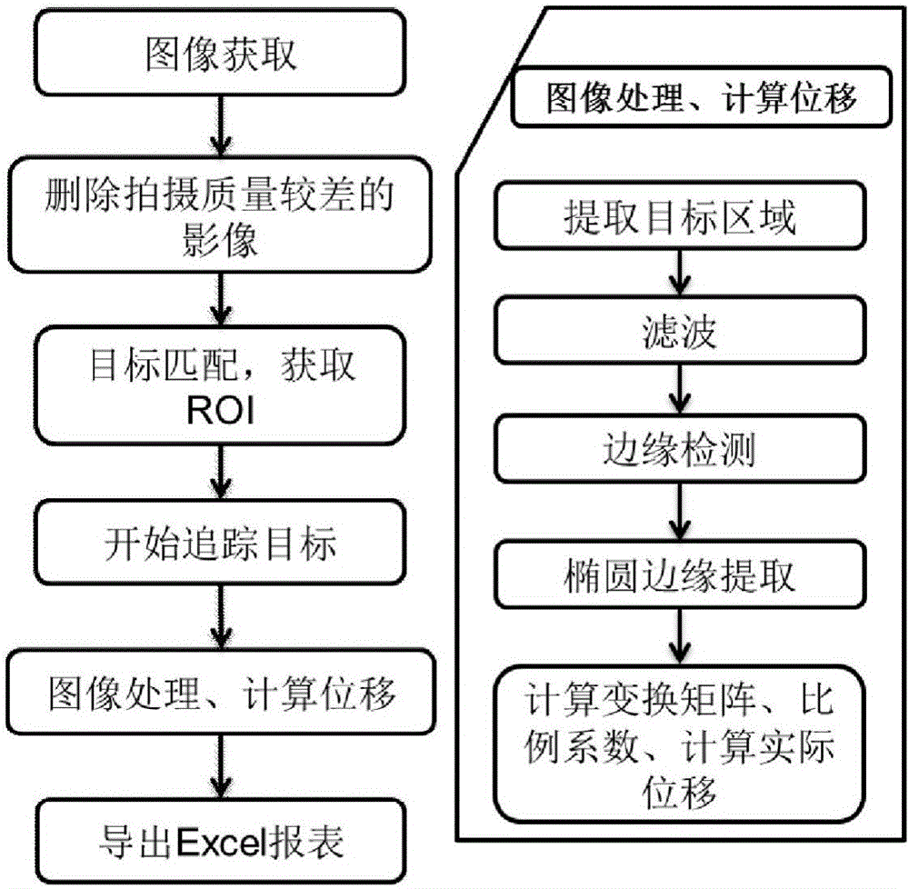
[0048] see figure 1 , the deformation monitoring method based on visual measurement of the present embodiment, comprising the following steps:

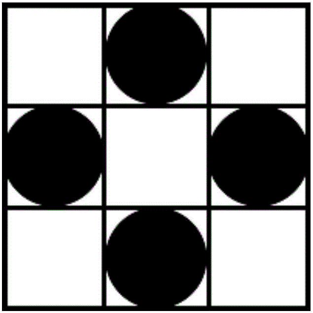
[0049] (1) Design the sign board for deformation monitoring. The sign board is a white base plate and four black discs set on the base plate. The boundaries of the discs cannot be tangent, intersected or coincident. is the first connecting line, and the connecting line between the centers of the remaining two wafers is the second connecting line, and the first connecting line and the second connecting line intersect perpendicularly. The design principle is as follows:

[0050] Assuming that the marker point moves horizontally by ΔX, the positioning accuracy is m x , the displacement accuracy is m Δx , the rela...


PUM


Abstract

The invention provides a deformation monitoring method based on vision measurement, and belongs to the technical field of deformation monitoring. The deformation monitoring method comprises the following steps that the mark plate of deformation monitoring is designed, wherein the mark plate is formed by a white baseplate and four black circular sheets which are arranged on the baseplate, the boundaries of the circular sheets cannot be tangent, intersected or overlapped, the connecting line of the center of the circle of the two circular sheets is a first connecting line, the connecting line of the center of the circle of the rest two circular sheets is a second connecting line, and the first connecting line and the second connecting line are perpendicular and intersected; characteristic contour models of different resolutions are established; subsequent images of different time points are acquired, and the elliptic center coordinates on the subsequent images, i.e. the coordinates of mark points, are accurately extracted; and the displacement of the mark points in the subsequent images is calculated, and the calculated displacement is corrected so that the actual displacement of the mark points is obtained. The deformation monitoring method based on vision measurement is easy to operate, high in degree of automation, low in cost, high in precision, simple in data processing and high in efficiency.

Description

technical field [0001] The present invention relates to the technical field of deformation monitoring, in particular to a deformation monitoring method based on vision measurement. Background technique [0002] Deformation monitoring is to use professional measuring instruments and supporting instruments to continuously observe the shape, size and position changes of deformed objects, which requires very high measurement accuracy and reliability. At present, the commonly used geodetic deformation monitoring technologies mainly include total station, GNSS, leveling, etc. These technologies have the advantages of high precision, but the cost is relatively high; deformation monitoring instruments such as displacement sensors need to be installed on the monitoring structure, and the construction is difficult larger. [0003] Vision measurement is a non-contact measurement method, which has the advantages of simplicity and low cost. With the development of digital camera techno...

Claims


Application Information

Patent Timeline
IPC IPC(8): G01B11/16
CPCG01B11/16
Inventor 邢磊戴吾蛟
Owner CENT SOUTH UNIV
Why Eureka
Try Eureka