Forming test mold for asphalt mixture rutting test piece

A technology for asphalt mixtures and test molds, which is applied in the direction of unloading devices, manufacturing tools, and preparation of test samples. It can solve problems such as poor thermal insulation effect, time-consuming and labor-intensive, loose mold connection parts, etc., and achieve small temperature fluctuations. The test process is simple and the effect of reducing test errors

Pending Publication Date: 2017-02-22
CHANGAN UNIV
4 Cites 3 Cited by

AI-Extracted Technical Summary

Problems solved by technology

[0005] 1) The heat preservation effect is poor. The forming test mold of the rutting specimen is made of high carbon steel or tool steel, and the heat conduction speed is fast, and it takes 5-6 minutes for the rutting specimen to be placed under the roller of the forming machine from the beginning of mold loading. The temperature loss in this process is about 15-20°C, and the number of rolling times generally requires 12 round-trips (24 times) to meet the requirements. The temperature loss in this process will be about 10-15°C, which makes it difficult to observe and control the forming temperature of the specimen, and it is different from the There is a big difference in the paving temperature in the actual construction process;
[0006] 2) During the molding process of the traditional rut sample mold, the side plates and the bottom plates of the four side plates of the mold are easy to bond with the asphalt mixtur...

Method used

The using method of the asphalt mixture rutting test piece forming test mold of the present invention is: in the test piece forming test process of the present invention, after the fixed shaft jack 4 is tightly engaged with the fixed shaft 5, the upper separation groove 1 and the The lower separation groove 2 is combined up and down, and the sliding locking plug 12 is pushed into the lock hole 13 in the locking groove 11, so that the positions of the upper separation groove 1 and the lower separation groove 2 are locked to form an open molding mold, and the dynamic temperature display 7 is opened. After the mold is heated to the specified temperature, the asphalt mixture is loaded into the mold and compacted. The high-temperature thermal insulation coating 9 can effectively prevent the temperature of the mold and the asphalt mixture from dropping during the molding process. The temperature sensor 6 tests the temperature of the asphalt mixture at different heights and It is displayed on the dynamic temperature display 7. After the compaction temperature is met, the mold is placed on the platform of the wheel mill through the heat insulation handle 3 and rolling is started. D...

Abstract

The invention discloses a forming test mold for an asphalt mixture rutting test piece. The forming test mold comprises an upper separating groove and a lower separating groove which are matched, wherein the upper separating groove and the lower separating groove are connected by a sliding locking device to form an opened container; a plurality of temperature sensors are arranged on the inner wall of the upper separating groove; the inner walls of the upper separating groove and the lower separating groove are respectively provided with an anti-sticking coating layer; and the outer walls and the bottom surfaces of the upper separating groove and the lower separating groove are respectively provided with a high-temperature heat-insulating coating layer. The forming test mold disclosed by the invention has the advantages that the demolding procedure after forming completion can be quickly realized; the upper separating groove and the lower separating groove can be separated only by unlocking the sliding locking device at the lower separating groove, so that the defect that the mold is taken out by using a rubber hammer to beat a bottom plate is overcome, the demolding efficiency is obviously improved, the disturbance to the test piece is less, and the influence of operation in the demolding process on all performances of the test piece is reduced.

Application Domain

Technology Topic

Image

  • Forming test mold for asphalt mixture rutting test piece
  • Forming test mold for asphalt mixture rutting test piece
  • Forming test mold for asphalt mixture rutting test piece

Examples

  • Experimental program(1)

Example Embodiment

[0028] The present invention will be further described in detail below with reference to the drawings and specific embodiments:
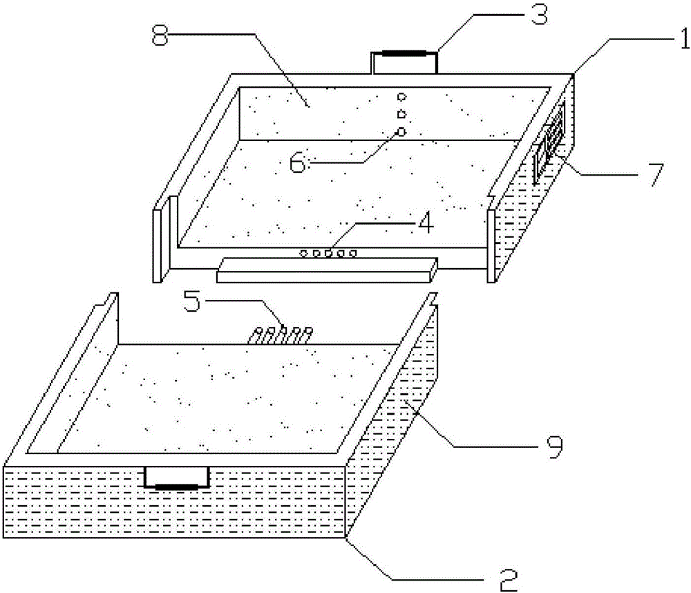
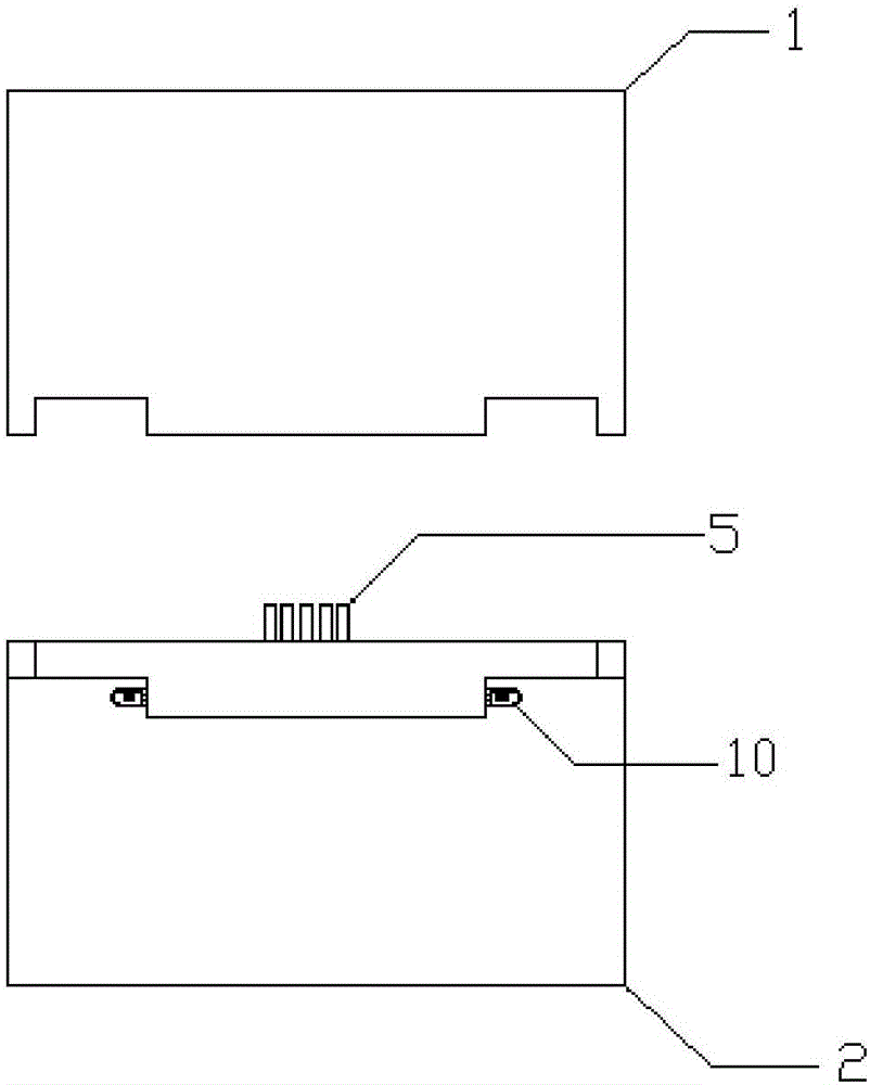
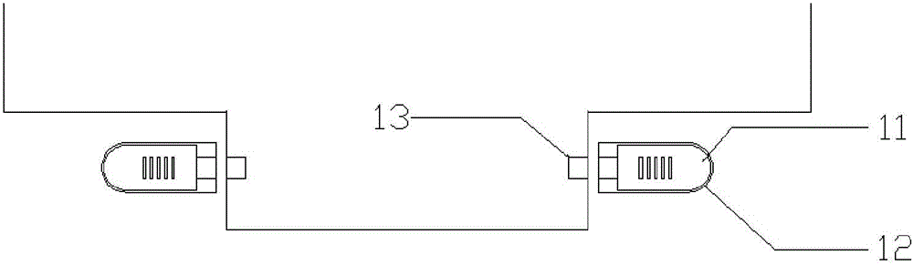
[0029] Such as figure 1 with figure 2 As shown, a separate asphalt mixture rutting test piece forming mold includes an upper separation groove 1, a lower separation groove 2, a heat insulation handle 3, a fixed shaft socket 4, a fixed shaft 5, a temperature sensor 6, a dynamic temperature display 7 , Anti-sticking coating 8, high temperature thermal insulation coating 9, sliding lock device 10. The sliding locking device 10 includes a locking groove 11, a sliding locking plug 12 and a locking hole 13. Among them, the upper separation groove and the lower separation groove are both a dustpan-like structure composed of three side plates and a bottom plate welded together, which can form an asphalt mixture rutting test piece forming mold with an upper opening after being connected. The upper separation groove 1 and the lower separation groove 2 are connected by a sliding locking device 10 to form an open container. The length of the open container is 300 mm, the width is 300 mm, and the height is 50 mm. The sliding locking device 10 is arranged on the lower separation groove 2.
[0030] See image 3 , The sliding locking device 10 includes a locking groove 11, a sliding locking plug 12 and a locking hole 13. The sliding locking plug 12 is arranged in the locking groove 11 and can be slid. The sliding locking plug 12 is pushed into the locking hole 13 for locking, and the sliding locking plug 12 is pushed out of the locking hole 13 to unlock.
[0031] A number of temperature sensors 6 are arranged on the inner wall of the upper separation tank 1, and a number of temperature sensors 6 are arranged along the inner wall of the upper separation tank 1 from top to bottom. The number of temperature sensors is 3, and the three temperature sensors 6 are located at a distance from the bottom of the upper separation tank. The distances are 5mm, 25mm, 45mm, and the effective range of each temperature sensor is -5℃~300℃, and can be accurate to 0.1℃.
[0032] The inner walls of the upper separation tank 1 and the lower separation tank 2 are both provided with an anti-stick coating 8. The anti-sticking coating 8 adopts polytetrafluoroethylene coating or ceramic coating, which can effectively prevent the adhesion phenomenon that occurs during the contact between the asphalt mixture and the mold.
[0033] The outer walls and bottom surfaces of the upper separation tank 1 and the lower separation tank 2 are both provided with a high-temperature thermal insulation coating 9. The high-temperature thermal insulation coating 9 is sprayed on the outer wall and bottom surface of the upper and lower separation tanks by high-temperature pressureless spraying. The high-temperature thermal insulation coating is a composite silicate thermal insulation coating. Thermal insulation coating is a kind of thermal insulation coating made of a variety of non-metallic mineral fibers containing aluminum and magnesium silicate as raw materials, doped with a certain amount of auxiliary materials and fillers, and added with chemical additives. It is a commercialized The product. After the prepared coating is applied by brushing or smearing on the heat preservation equipment, drying, curing and forming, it can form an electrostatic-type inorganic heat insulation and heat preservation coating which is connected to the solid substrate and has a closed pore network structure. The composite silicate thermal insulation coating has excellent thermal insulation effect, high-temperature chemical stability and corrosion resistance, and is economical and energy-saving.
[0034] The side wall of the upper separation groove 1 is provided with a stepped structure, and the upper part of the stepped structure is provided with two lock holes and three fixed shaft insertion holes 4, the fixed shaft insertion hole 4 is arranged in the middle of the upper separation groove 1, and The spacing is 10mm, the diameter of each fixed shaft hole is 5mm, and the depth is 15mm. Several fixed shafts are symmetrically distributed in the middle position of the lower separation groove 2, and the position and size correspond to the fixed shaft sockets, ensuring that the upper separation groove 1 and the lower separation groove 2 can be accurately engaged and made without error during the forming process of the asphalt mixture rutting specimen move.
[0035] The side wall of the lower separation groove 2 opposite to the upper separation groove 1 is also provided with a stepped structure, and the upper part of the stepped structure is provided with a fixed shaft 5 matching the fixed shaft insertion hole 4.
[0036] The side wall of the upper separation tank 1 is provided with a temperature display 7 connected to the temperature sensor 6, which can dynamically display the temperature of 3 different height points on the inner wall of the mold, and the side wall of the upper separation tank 1 is provided with a removable lithium battery slot.
[0037] The side walls of the upper separation tank 1 and the lower separation tank 2 are respectively provided with a rectangular heat insulation handle 3.
[0038] The method of using the forming test mold of the asphalt mixture rutting test piece of the present invention is as follows: in the test piece forming experiment process of the present invention, after the fixed shaft insertion hole 4 and the fixed shaft 5 are closely engaged, the upper separation groove 1 and the lower separation groove 2 Combine up and down, push the sliding locking plug 12 into the lock hole 13 in the locking groove 11 to lock the position of the upper separation groove 1 and the lower separation groove 2 to form an open molding mold, open the dynamic temperature display 7 and heat the mold to After the specified temperature, the asphalt mixture is loaded into the mold and compacted. The high-temperature thermal insulation coating 9 can effectively prevent the temperature of the mold and asphalt mixture from falling during the molding process. The temperature sensor 6 measures the temperature of the asphalt mixture at different heights and displays it in the dynamic state. On the temperature indicator 7, after the compaction temperature is met, the mold is placed on the wheel mill platform through the heat-insulating handle 3 and rolling begins. During the rolling process, the dynamic temperature indicator 7 observes the temperature change of the test piece, and test each bituminous mixture The actual molding temperature range and rolling times of the piece are recorded on the label and pasted on the surface of the test piece after the molding is completed. The dynamic temperature indicator 7 is turned off. After the temperature of the test piece cools down at room temperature, the sliding locking device 10 is opened (method The same as the above locking method), the anti-stick coating 8 can prevent the adhesion between the asphalt mixture and the mold. The two separation grooves are separated by pulling the heat insulation handles 3 at both ends of the upper separation groove 1 and the lower separation groove 2 , Take out the asphalt mixture sample.
[0039] The above content is a further detailed description of the present invention in conjunction with specific preferred embodiments, and it cannot be considered that the specific implementation of the present invention is limited to these descriptions. For those of ordinary skill in the technical field to which the present invention belongs, several simple deductions or substitutions can be made without departing from the concept of the present invention, which should be regarded as falling within the protection scope of the present invention.

PUM

PropertyMeasurementUnit
Diameter5.0mm
Depth15.0mm
tensileMPa
Particle sizePa
strength10

Description & Claims & Application Information

We can also present the details of the Description, Claims and Application information to help users get a comprehensive understanding of the technical details of the patent, such as background art, summary of invention, brief description of drawings, description of embodiments, and other original content. On the other hand, users can also determine the specific scope of protection of the technology through the list of claims; as well as understand the changes in the life cycle of the technology with the presentation of the patent timeline. Login to view more.

Similar technology patents

Classification and recommendation of technical efficacy words

  • Good insulation effect
  • Small temperature fluctuation range

Method for determining organic matters in soil

InactiveCN104280512AHeating evenlySmall temperature fluctuation rangeChemical analysis using titrationSoil organic matterHeating time
Owner:SHENYANG INST OF APPLIED ECOLOGY - CHINESE ACAD OF SCI

Temperature control system for non-Newtonian high-viscosity fluid conveying

PendingCN111664360ASmall temperature fluctuation rangeEnsure consistencyPipe heating/coolingPipeline systemsEngineeringMechanics
Owner:重庆海浦洛自动化科技有限公司
Why Eureka
Try Eureka