All-optical display device and method

A light display and display unit technology, applied in optics, optical components, instruments, etc., can solve the problems of low viewing quality, inconvenient viewing, poor viewing effect, etc., and achieve the effect of convenient viewing, convenient viewing, and prevention of dizziness

Inactive Publication Date: 2017-02-22
胡晓明
View PDF5 Cites 0 Cited by
  • Summary
  • Abstract
  • Description
  • Claims
  • Application Information

AI Technical Summary

Problems solved by technology

[0004] Aiming at the problems of inconvenient viewing, low viewing quality, and poor viewing effect existing in the stereoscopic scene display technology in the prior art, the technical problem to be solved by the present invention is to provide a plenoptic display device and method that can enhance the user's stereoscopic view. The viewing experience of the scene

Method used


Image

  • All-optical display device and method
  • All-optical display device and method
  • All-optical display device and method

Examples


Embodiment 1

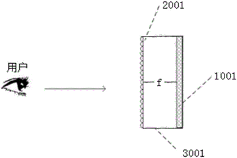
[0038] see figure 1 , is a schematic structural diagram of a plenoptic display device provided by an embodiment of the present invention, as shown in figure 1 The plenoptic display device shown includes a display unit 1001 , a plenoptic lens 2001 and a housing 3001 . Wherein, the shown display unit 1001 and the plenoptic lens 2001 are arranged in the housing 3001; along the display direction of the display unit 1001, the plenoptic lens 2001 is arranged in front of the display unit 1001; what needs to be explained Yes, the display direction of the display unit 1001 can be understood as the direction in which the display unit 1001 emits light.

[0039] Wherein, the display unit 1001 is a unit capable of converting all-optoelectronic signals into visual signals. During specific implementation, the display unit 1001 may be any one of a CRT display unit, an LCD display unit, an LED display unit and a PDP display unit. Moreover, depending on the display scene, you can choose to u...

Embodiment 2

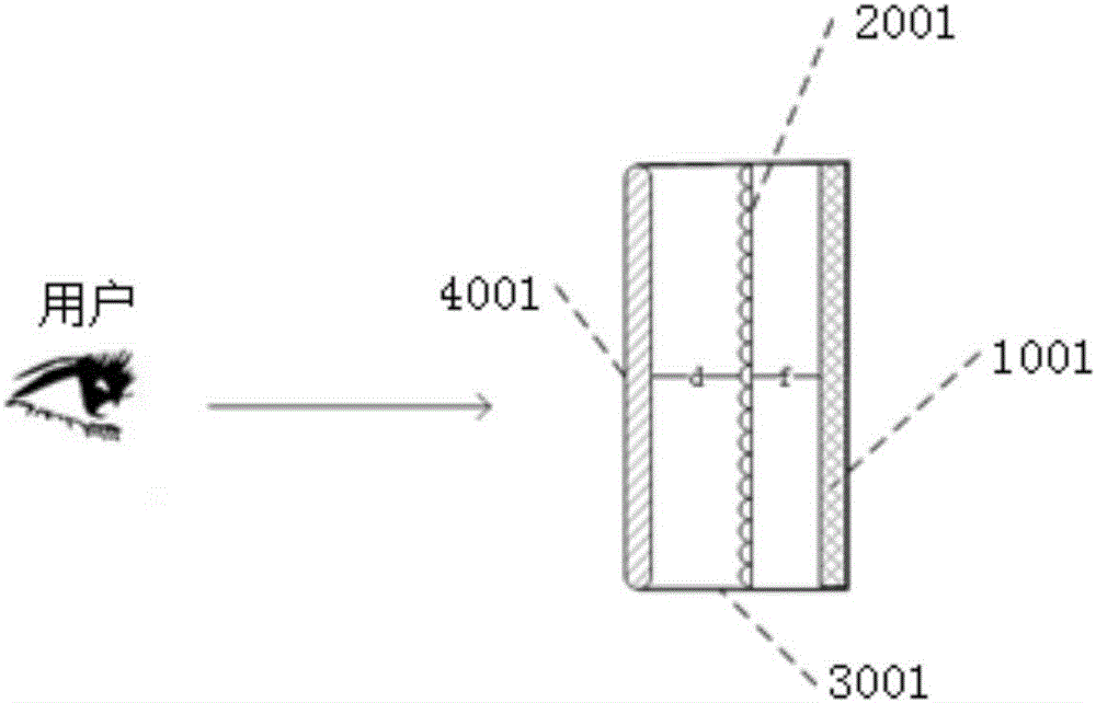
[0053] see image 3 , is a schematic structural diagram of another all-optical display device provided by an embodiment of the present invention, as shown in image 3 The shown plenoptic display device includes a display unit 1001, a plenoptic lens 2001 and an imaging panel 4001; wherein, the display unit 1001 and the plenoptic lens 2001 are all arranged in the housing 3001; along the display unit 1001 To display the direction, the plenoptic lens 2001 is arranged in front of the display unit 1001 . The difference between the embodiment of the present invention and the first embodiment is that the plenoptic display device of the embodiment of the present invention further includes an imaging panel 4001, and the imaging panel 4001 is arranged in the housing 3001, and is arranged on the plenoptic lens 2001 Front; Preferably, the central axis of the imaging panel 4001 coincides with the central axis of the plenoptic lens 2001 .

[0054] In actual implementation, the imaging pane...


PUM


Abstract

The invention provides an all-optical display device and an all-optical display method. The all-optical display device comprises a housing, an all-optical eyeglass and a display unit, wherein the display unit is used for converting an all-optical electron signal; the all-optical glass is arranged in front of the display unit; a lens array is arranged on the all-optical glass; lenses are arranged corresponding to pixel unit clusters on the display unit; corresponding pixel unit clusters are covered with imaging surfaces of the lenses; the center of each pixel unit cluster is positioned on a focal plane a corresponding lens. As light information of a same position in different directions is recorded in all-optical data, the direction information of light can be reduced by using the all-optical glass; scenes can be reduced in a natural light approximate mode, no wearing assistant equipment is needed, and thus watching convenience can be brought to users; in addition, scene reduction of the all-optical eyeglass needs no techniques of prisms, light splitting and the like, so that view jumping, color brightness reduction, angle limit and dizziness can be prevented, and the viewing quality and the viewing effect can be effectively improved; in addition, reduced images can be fused with the natural environment, and the user experience can be improved.

Description

technical field [0001] The invention relates to the technical field of imaging equipment, in particular to a plenoptic display device and method. Background technique [0002] With the development of virtual and augmented reality technologies, there are always many bottlenecks in the display of virtual reality or augmented reality scenes. At present, binocular 3D source data is usually displayed through a display or a projection device. The user wears related glasses with matching lenses, and through the selection of light by the glasses, different content is presented in the left and right eyes respectively to obtain a visible three-dimensional scene. Among them, for color filter technologies such as red-green 3D and red-blue 3D, users can see three-dimensional scenes with red-green or red-blue glasses; for active and passive polarization technologies, users can also see three-dimensional scenes with polarized glasses. Another way to display stereoscopic scenes is naked-ey...

Claims


Application Information

Patent Timeline
Patent Type & Authority Applications(China)
IPC IPC(8): G02B27/22
CPCG02B30/27
Inventor 胡晓明
Owner 胡晓明
Why Eureka
Try Eureka