
A 3D mold for ultrasonography showing tiny thyroid nodules

A thyroid, tiny technology, applied in the direction of ultrasound/sonic/infrasonic diagnosis, ultrasound/sonic/infrasonic Permian technology, ultrasound/sonic/infrasonic image/data processing, etc., can solve waste of manpower and material resources, unable to judge, ultrasound Physicians and surgeons lack the ability of ultrasound doctors, etc., to achieve the effect of simple operation, simple structure, and convenient observation of thyroid micronodules

Active Publication Date: 2019-04-30
浙江环艺电子科技有限公司
View PDF5 Cites 1 Cited by
  • Summary
  • Abstract
  • Description
  • Claims
  • Application Information

AI Technical Summary

Problems solved by technology

[0002] Since the popularization and application of high-frequency ultrasound, the detection rate of thyroid micronodules has become higher and higher, and many malignant tumors of the thyroid gland can be removed in time. However, most surgeons judge patients' thyroid glands based on the written description of the sonographer. The location of tiny nodules is also removed by experience (such as hand feeling, etc.) during surgery. If the nodules are too small or the texture of the nodules is similar to thyroid tissue, the surgeon cannot judge which piece to remove during the operation. Thyroid tissue, even after resecting suspected thyroid tissue based on experience, there is no confidence that the tiny nodules have been removed, so it is common to ask the sonographer to bring an ultrasound machine to the operating table to check whether the patient’s thyroid nodules have been resected , This is a waste of manpower and material resources. The fundamental problem is the lack of effective communication between the sonographer and the surgeon, that is, the sonographer cannot accurately feed back the facts he sees to the surgeon performing the operation.

Method used


Image

  • A 3D mold for ultrasonography showing tiny thyroid nodules
  • A 3D mold for ultrasonography showing tiny thyroid nodules

Examples


Embodiment Construction

[0013] The following will clearly and completely describe the technical solutions in the embodiments of the present invention with reference to the accompanying drawings in the embodiments of the present invention. Obviously, the described embodiments are only some, not all, embodiments of the present invention. Based on the embodiments of the present invention, all other embodiments obtained by persons of ordinary skill in the art without making creative efforts belong to the protection scope of the present invention.

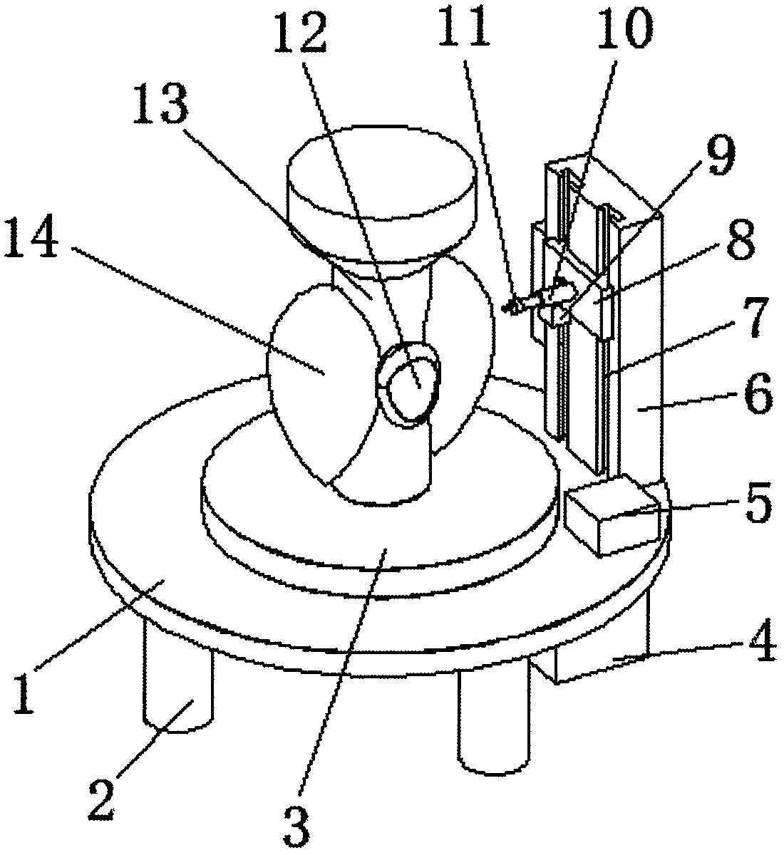
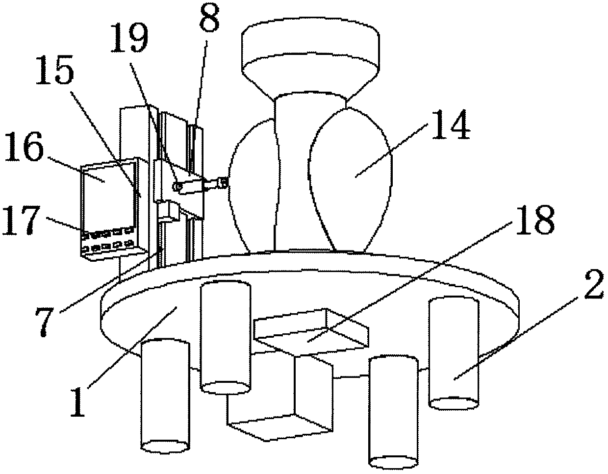
[0014] see Figure 1-2 , the present invention provides a technical solution: a three-dimensional mold for ultrasonography to display tiny thyroid nodules, including a support plate 1, a rotating table 3 is provided at the center of the upper surface of the supporting plate 1, and a cervical spine is provided at the center of the upper surface of the rotating table 3. Model 13, both sides of the cervical spine model 13 are equipped with silicone thyroid models...


PUM


Abstract

The invention discloses a three-dimensional mold of displaying thyroid mini nodules in an ultrasound department. A rotating platform is arranged at a center of an upper surface of a supporting plate. A center of an upper surface of the rotating platform is provided with a cervix model. Two sides of the cervix model are provided with uniform silica gel thyroid models. Through the silica gel thyroid models, clear observation can be performed. A lower surface of the supporting plate is provided with a deceleration motor. The deceleration motor drives the rotating platform to rotate. Through rotation of the rotating platform, the silica gel thyroid models are adjusted so that thyroid mini nodule observation is convenient. An electric telescoping rod is provided with a marking head. Through the marking head, the silica gel thyroid models are marked so that the thyroid mini nodule observation is clear. By using the three-dimensional mold of displaying the thyroid mini nodules in the ultrasound department, the structure is simple and operation is convenient; and a sonographer can accurately feed back a fact to a surgeon who performs an operation, which is convenient for the surgeon to perform the operation.

Description

technical field [0001] The invention relates to the technical field of medical equipment, in particular to a three-dimensional mold for displaying tiny thyroid nodules in an ultrasound department. Background technique [0002] Since the popularization and application of high-frequency ultrasound, the detection rate of thyroid micronodules has become higher and higher, and many malignant tumors of the thyroid gland can be removed in time. However, most surgeons judge patients' thyroid glands based on the written description of the sonographer. The location of tiny nodules is also removed by experience (such as hand feeling, etc.) during surgery. If the nodules are too small or the texture of the nodules is similar to thyroid tissue, the surgeon cannot judge which piece to remove during the operation. Thyroid tissue, even after resecting suspected thyroid tissue based on experience, there is no confidence that the tiny nodules have been removed, so it is common to ask the sono...

Claims


Application Information

Patent Timeline
Patent Type & Authority Patents(China)
IPC IPC(8): G09B23/28A61B8/08
CPCA61B8/085G09B23/28
Inventor 孙丽华王晓刘正
Owner 浙江环艺电子科技有限公司
Learn More