OLED display panel with narrow frame structure

A display panel and narrow frame technology, which is applied in the OLED field, can solve the problems of occupying a large space and increasing the frame of OLED displays, etc., and achieve the effect of increasing strength, ensuring brightness, and increasing size

Active Publication Date: 2017-02-22
GUANGZHOU GOVISIONOX TECH CO LTD
View PDF4 Cites 3 Cited by
  • Summary
  • Abstract
  • Description
  • Claims
  • Application Information

AI Technical Summary

Problems solved by technology

[0002] like figure 1 As shown, the OLED light-emitting panel includes a display area 1 and a frame area 2. The frame area 2 includes an upper frame 21, a lower frame 22, a left frame 23, and a right frame 24. Metal wiring 3 is provided in the frame area. The cathode of the display area 1 11 extends to the left frame 23 and the right frame 24, wherein the metal wire 3 is used to transmit signals to the cathode 11, and the current transmitted by the external circuit to the OLED through the metal wire is directly related to the display brightness of the screen, so in order to reduce Impedance, the metal trace 3 is usually wide and circles around the display area, especially for large-sized display devices, its line width occupies half of the frame, thus occupying a larger position around the frame of the OLED display, which in turn increases the OLED monitor border

Method used


Image

  • OLED display panel with narrow frame structure
  • OLED display panel with narrow frame structure
  • OLED display panel with narrow frame structure

Examples


Embodiment 1

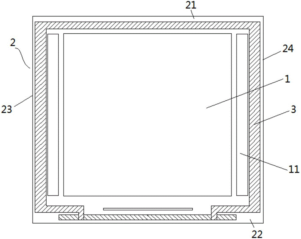
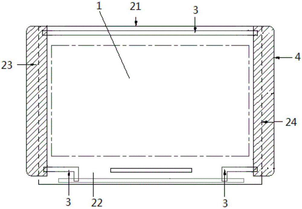
[0025] figure 2 The frame area 2 in the display area 2 includes an upper frame 21, a lower frame 22, a left frame 23, and a right frame 24. The metal wires 3 are respectively arranged in the upper frame 21 and the lower frame 22. The cathode (not shown in the figure) in the display area 1 out) is connected to the metal trace 3 through the anode. Both ends of the line 3 are electrically connected. Of course, according to different frame structures of the OLED display panel, the metal wires 3 can also be arranged on the left and right frames, and the conductive tape can be used instead of the metal wires in the upper and lower frames, so that the upper and lower frames can be made narrower.

[0026] Here, the conductive tape 4 can be bonded to cover the blank area on the back of the display area 1, using a fully covered structure or a partially covered structure, thereby reducing the impedance and ensuring that the metal traces can transmit sufficient current to the OLED displ...

Embodiment 2

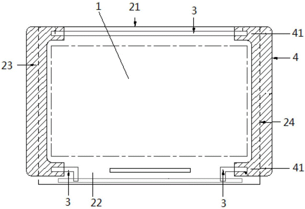
[0029] Different from Embodiment 1, in this embodiment, a raised structure 41 is formed on the upper and lower ends of the conductive tape 4 on the left frame 23 and the right frame 24 respectively, as image 3 As shown, the protruding structure 41 is located at both ends of the upper frame 21 and the lower frame 22 , and forms an electrical connection with the metal wiring 3 .

[0030] The width of the protruding structure 41 is greater than the width of the metal trace 3 . Compared with the width of the metal traces in the upper and lower frames, the conductive tape is wider to ensure that the ends of the metal traces are completely covered by the conductive tape, and because the conductive tape covers the blank area on the back of the OLED display panel, reducing the The small impedance ensures that the metal traces transmit enough current to the OLED display area, thus ensuring the brightness of the display.

[0031] Preferably, the upper end of the conductive tape 4 is f...


PUM


Abstract

The invention discloses an OLED display panel with a narrow frame structure. The OLED display panel with the narrow frame structure comprises a display area and a frame area positioned at the periphery of the display area, wherein a metal wire is arranged on one of opposite frames in the frame area; a cathode in the display area is connected with the metal wire through an anode; a conductive adhesive tape is arranged on the back side of the display area; and the two ends of the conductive adhesive tape are electrically connected with the two ends of the metal wire in the two opposite frames after being bent. The conductive adhesive tape is adhered to the back side of the OLED display panel, the conductive adhesive tape is bent by the left side and the right side of the display panel onto one of the opposite frames, the conductive adhesive tape is electrically connected with the two ends of the metal wire on the other one of opposite frames separately, and the conductive adhesive replaces the metal wire on one of the opposite frames, so that the size of the frame area is narrowed and the size of the display area is increased.

Description

technical field [0001] The invention relates to the technical field of OLEDs, in particular to an OLED display panel with a narrow frame structure. Background technique [0002] Such as figure 1 As shown, the OLED light-emitting panel includes a display area 1 and a frame area 2. The frame area 2 includes an upper frame 21, a lower frame 22, a left frame 23, and a right frame 24. Metal wiring 3 is provided in the frame area. The cathode of the display area 1 11 extends to the left frame 23 and the right frame 24, wherein the metal wire 3 is used to transmit signals to the cathode 11, and the current transmitted by the external circuit to the OLED through the metal wire is directly related to the display brightness of the screen, so in order to reduce Impedance, the metal trace 3 is usually wide and circles around the display area, especially for large-sized display devices, its line width occupies half of the frame, thus occupying a larger position around the frame of the O...

Claims


Application Information

Patent Timeline
Patent Type & Authority Applications(China)
IPC IPC(8): H01L51/52H01L51/56
CPCH10K50/84H10K2102/302H10K71/00
Inventor 卢丹王向前朱修剑
Owner GUANGZHOU GOVISIONOX TECH CO LTD
Why Eureka
Try Eureka