
Angled multi-core connectors for motors and motor controllers

A motor controller and connector technology, which is used in conductive connection, connection, multi-core cable end components, etc., can solve the problems of power components not on the same mounting surface, accumulated tolerances of multi-core power components, and inability to achieve integration. Achieve the effect of reducing secondary shielding treatment, ensuring effective contact and saving labor costs

Active Publication Date: 2019-01-08
SICHUAN YONGGUI SCI & TECH CO LTD
View PDF7 Cites 0 Cited by
  • Summary
  • Abstract
  • Description
  • Claims
  • Application Information

AI Technical Summary

Problems solved by technology

[0002] Usually, the motor wires are routed at 180°, but in the actual wiring process, the motor wires need to be bent (even 90°), and the bending position is the stress concentration point. During the thermal expansion and cold contraction of the cable, the rubber may crack, which poses a safety hazard. , in order to meet this requirement, it is necessary to design a 90° outlet structure
Existing motors and motor controllers mainly use cable crimping copper tube terminals or hard copper bars to achieve electrical connection. In order to achieve shielding effect, the former mainly uses shielded pipe joints or shielded lead wires for grounding, and the latter is designed with a corresponding shielding structure. , so each has its own defects. The former is unable to achieve integration, and the latter is designed to lead out at 90°. There will be cumulative tolerances in multi-core power components, resulting in power components that are not on the same mounting surface, difficult to assemble, and low in efficiency.

Method used


Image

  • Angled multi-core connectors for motors and motor controllers
  • Angled multi-core connectors for motors and motor controllers
  • Angled multi-core connectors for motors and motor controllers

Examples


Embodiment Construction

[0034] All features disclosed in this specification, or steps in all methods or processes disclosed, may be combined in any manner, except for mutually exclusive features and / or steps.

[0035] Any feature disclosed in this specification (including any appended claims, abstract and drawings), unless expressly stated otherwise, may be replaced by alternative features which are equivalent or serve a similar purpose. That is, unless expressly stated otherwise, each feature is one example only of a series of equivalent or similar features.

[0036] The specific implementation manners of the present invention will be described in detail below in conjunction with the drawings and embodiments.

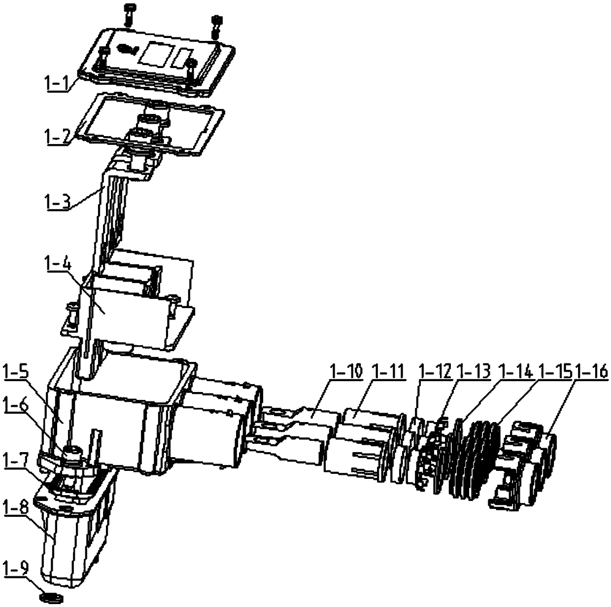
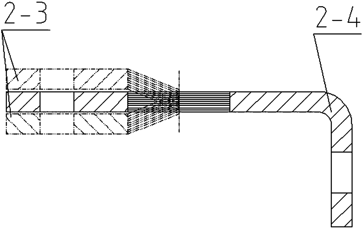
[0037] Such as Figure 1 to Figure 10 , according to an embodiment of the present invention, this embodiment discloses a kind of bent multi-core connector for a motor and a motor controller, which includes a cover plate 1-1, a sealing gasket 1-2, a soft copper bar 1-3, and an insulating inst...


PUM


Abstract

The invention discloses a multi-core angle connector for a motor and a motor controller. The multi-core angle connector comprises a shell, an insulation mounting plate, soft copper bars, terminal blocks, insulators, shielding rings, shielding pressure sleeves, a cover plate, a seal gasket and a seal ring. When cables are connected into the connector, the cables are stripped to exposure shielding layers and then connected with the terminal blocks, and the shielding rings are connected to the cables through the shielding pressure sleeves by pressing and clamped on the shell; the insulators sleeve the terminal blocks and pressed into the shell by interference fit; the insulation mounting plate is detachably fixed to the shell; the soft copper bars and the terminal blocks are detachably fixed to the insulation mounting plate; the seal gasket is arranged between the shell and the cover plate; the seal ring is arranged on a mounting surface of the shell. The multi-core angle connector has advantages that product integration is realized, and secondary shielding processing is reduced; a power part is locally bendable, the defect that the copper bars are not coplanar due to tolerance accumulation is improved, effective contact of joint faces of the copper bars is guaranteed, and accordingly high reliability in connection is realized.

Description

technical field [0001] The invention relates to the technical field of electric vehicle connectors, in particular to a bent multi-core connector for electric vehicle motors and motor controllers. Background technique [0002] Usually, the motor wires are routed at 180°, but in the actual wiring process, the motor wires need to be bent (even 90°), and the bending position is the stress concentration point. During the thermal expansion and cold contraction of the cable, the rubber may crack, which poses a safety hazard. , in order to meet this requirement, it is necessary to design a 90° outlet structure. Existing motors and motor controllers mainly use cable crimping copper tube terminals or hard copper bars to achieve electrical connection. In order to achieve shielding effect, the former mainly uses shielded pipe joints or shielded lead wires for grounding, and the latter is designed with a corresponding shielding structure. , so each has its own defects. The former cannot...

Claims


Application Information

Patent Timeline
Patent Type & Authority Patents(China)
IPC IPC(8): H01R11/11H01R9/03
CPCH01R9/03H01R11/11
Inventor 喻通
Owner SICHUAN YONGGUI SCI & TECH CO LTD
Learn More