Phase control method and control circuit used for large array element coherent combination

A phase control circuit and coherent combination technology, applied in circuits, electrical components, laser components, etc., can solve the problems of SPGD algorithm and single-frequency dithering algorithm control bandwidth reduction, limited number of control channels, cumbersome circuit debugging, etc., to achieve Increase the maximum number of control channels, increase the control bandwidth, and facilitate hardware implementation

Active Publication Date: 2017-02-22
NAT UNIV OF DEFENSE TECH
View PDF4 Cites 10 Cited by
  • Summary
  • Abstract
  • Description
  • Claims
  • Application Information

AI Technical Summary

Problems solved by technology

[0007] (1) The control bandwidth of the SPGD algorithm and the single-frequency dithering algorithm decreases rapidly with the bandwidth of the number of control channels;
[0008] (2) The multi-jitter algorithm requires multiple jitter frequencies, the circuit debugging is cumbersome, and the requirements for the response frequency range of the phase modulator are too high;
[0009] (3) The existing phase control circuit is based on a single programmable chip, the number of control channels is limited, and it is difficult to realize the phase control of a coherent combination system with hundreds of channels.

Method used


Image

  • Phase control method and control circuit used for large array element coherent combination
  • Phase control method and control circuit used for large array element coherent combination
  • Phase control method and control circuit used for large array element coherent combination

Examples


Embodiment Construction

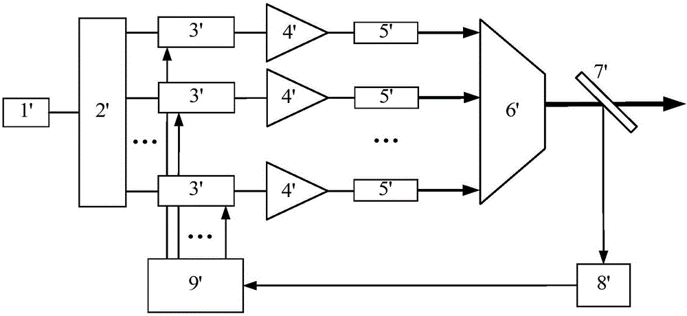
[0036] Laser coherent combining systems such as figure 1 As shown, there are M×N phase modulators in total, and the corresponding number of laser paths is also M×N. The modulation signal for the phase control algorithm is structured as follows:

[0037] The orthogonal coding single-frequency dithering algorithm outputs a total of M groups of signals, and the i-th group of signals is formed as follows:

[0038]

[0039] h M (i, k) is the value of row i and column k of Hadamard matrix of order m, k=1, 2, . . . , M.

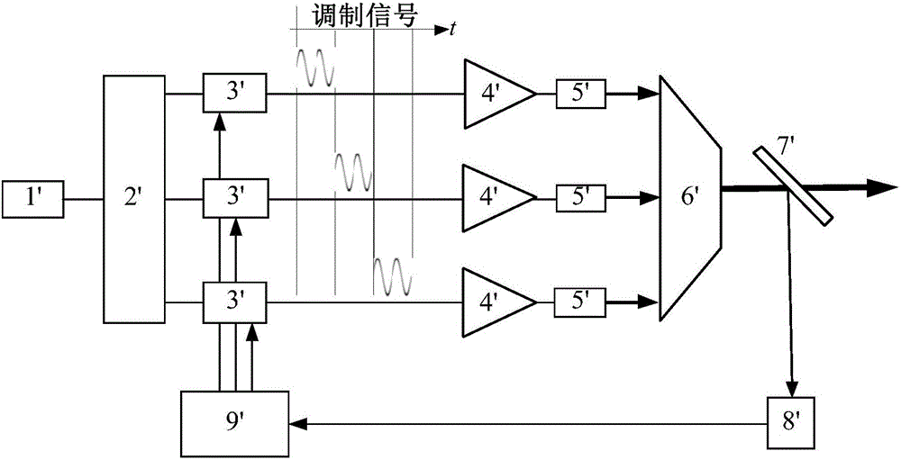
[0040] From (j-1)T to jT time, apply the modulation signal y to the (i-1)×N+j phase modulator i (t), i takes a value from 1 to M, j takes a value from 1 to N; and repeats the above process until the phase control circuit is closed.

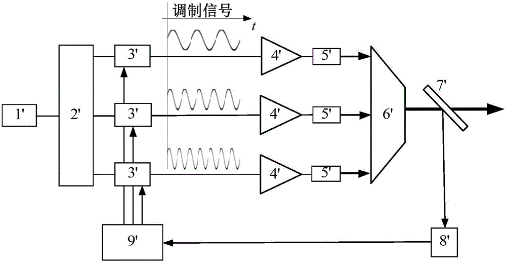
[0041] The modulation signal in the phase control algorithm of the phase control method of the present invention is illustrated below by taking the 4×3 laser coherent combination system as an example, such as Figure 5 Shown:

[...


PUM


Abstract

The invention provides a phase control method used for large array element coherent combination. The phase control method is characterized in that a modulation signal of a phase control algorithm is subjected to orthogonal coding and single-frequency modulation; compared with a multi-dithering algorithm, debugging signals with a plurality of frequencies are not needed, so that the algorithm is simplified and hardware is convenient to realize; compared with a single-dithering algorithm, the quantity of paths subjected to phase debugging within a certain time period is increased and the control bandwidth is improved. The invention further provides a phase control circuit used for the large array element coherent combination; the phase control circuit comprises a programmable chip 1, a digital to analog converter 3, a control signal conditioning circuit 4, an analog to digital converter 5 and an input signal conditioning circuit 6, and is characterized by further comprising a multiplexer 2. Under the condition that the number of output pins of the programmable chip 1 is limited, the maximum control path quantity of a control circuit is improved, and phase control of a hundred-path-level large array element coherent combination system can be realized.

Description

technical field [0001] The invention relates to coherent combining of lasers, in particular to a phase control method and a control circuit for coherent combining of large array elements. Background technique [0002] Laser coherent combination technology can break through the limit of single-channel laser output power, improve laser power and brightness, and is currently a research hotspot in the field of high-energy laser technology. The active phase control-based master oscillator power amplifier (English name is Master Oscillator Power Amplifier, MOPA for short) structure is a commonly used laser coherent combining system (see invention patent CN 1688069 A). The system structure is as figure 1 As shown (refer to literature: Liu Zejin, et al. Research on coherent combining of fiber lasers with active phase control. China Laser, 2009,36(3):518-524.), the system mainly includes seed laser 1 / , laser beam splitter 2 / , phase modulator 3 / , laser amplifier 4 / , Laser...

Claims


Application Information

Patent Timeline
Patent Type & Authority Applications(China)
IPC IPC(8): H01S3/10
CPCH01S3/10053
Inventor 粟荣涛尹明杨保来王小林周朴马阎星马鹏飞司磊许晓军陈金宝刘泽金
Owner NAT UNIV OF DEFENSE TECH
Why Eureka
Try Eureka