Railway safety monitoring system and monitoring method

A railway safety and monitoring system technology, applied in the transmission system, electromagnetic wave transmission system, electrical components, etc., can solve the problem of unable to provide information for optical cable fault prevention, reduce application cost and equipment installation time, high monitoring sensitivity, positioning high precision effect

Active Publication Date: 2017-02-22
NANJING PIONEER AWARENESS INFORMATION TECH CO LTD
View PDF7 Cites 9 Cited by
  • Summary
  • Abstract
  • Description
  • Claims
  • Application Information

AI Technical Summary

Problems solved by technology

Most of the existing detection technologies can only detect and locate the faults of communication optical cables or cables alone
At the same time, these technologies all play a role after the fault occurs, but cannot provide information for the prevention of optical cable faults

Method used


Image

  • Railway safety monitoring system and monitoring method
  • Railway safety monitoring system and monitoring method
  • Railway safety monitoring system and monitoring method

Examples


Embodiment 1

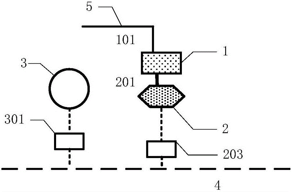
[0058] Embodiment 1 is a system structure of a single single optical port phase-sensitive optical time domain reflectometer and a single data processing unit, such as figure 1 shown. It includes a first phase sensitive optical time domain reflectometer 1, a first optical port 101, a first data processing unit 2, a server 3, a first sensing optical fiber 5, a first coaxial cable 201, a first network photoelectric transceiver 203, The fourth network photoelectric transceiver 301 and communication optical cable 4 .

[0059] The first phase sensitive optical time domain reflectometer 1 is connected to the first sensing fiber 5 through the first optical port 101 . The first sensing optical fiber 5 may be a core of an existing communication optical cable along the railway. The electrical signal output of the first phase sensitive optical time domain reflectometer 1 is connected to the first data processing unit 2 through the first coaxial cable 201 . The output end of the first d...

Embodiment 2

[0060] Embodiment 2 is a system structure of multiple dual-optical-port phase-sensitive optical time-domain reflectometers and multiple data processing units, such as Figure 7 shown. Including a first phase-sensitive optical time-domain reflectometer 1, a second phase-sensitive optical time-domain reflectometer 11, a third phase-sensitive optical time-domain reflectometer 21, a first optical port 101, a second optical port 102, and a third optical port 1101, fourth optical port 1102, fifth optical port 2101, sixth optical port 2102, first data processing unit 2, second data processing unit 12, third data processing unit 22, server 3, first sensing optical fiber 5 , the second sensing fiber 6, the third sensing fiber 15, the fourth sensing fiber 16, the fifth sensing fiber 25, the sixth sensing fiber 26, the first coaxial cable 201, the second coaxial cable 202, The third coaxial cable 1201, the fourth coaxial cable 1202, the fifth coaxial cable 2201, the sixth coaxial cable 22...

Embodiment 3

[0062] Embodiment three is a system structure of a single dual-optical-port phase-sensitive optical time-domain reflectometer and a single data processing unit, such as Figure 8 shown. Including a first phase sensitive optical time domain reflectometer 1, a first optical port 101, a second optical port 102, a first data processing unit 2, a server 3, a first sensing fiber 5, a second sensing fiber 6, a first A coaxial cable 201 , a second coaxial cable 202 , a first network optical transceiver 203 , a fourth network optical transceiver 301 and a communication optical cable 4 .

[0063] The first phase sensitive optical time domain reflectometer 1 is connected to the first sensing fiber 5 and the second sensing fiber 6 through the first optical port 101 and the second optical port 102 respectively. The first sensing optical fiber 5 and the second sensing optical fiber 6 may be respectively a core of an existing communication optical cable along the railway. The two electrica...


PUM


Abstract

the invention provides a railway safety monitoring system and monitoring method. The system comprises one and more phase-sensitive optical time-domain reflectometers arranged along a railway, corresponding data processing units, coaxial cables, a first network photoelectric transceiver, a communication optical cable along the railway, a second network photoelectric transceiver, and a server. According to the system and method, the railway safety is monitored by employing the conventional communication optical cable, the cost is low, passive distributed detection is realized, electromagnetic interference resistance is achieved, the development of the field of the railway optical cable safety monitoring system is greatly promoted, and good guarantee is provided for monitoring of railway train operation, infrastructure safety, and illegal authorization construction.

Description

technical field [0001] The invention relates to railway safety, in particular to a railway safety monitoring system and monitoring method. Background technique [0002] With the development of my country's railway industry, the importance of railway traffic safety and communication is becoming more and more significant. The safety status of railway communication optical cables is related to the normal operation of the entire railway transportation. However, illegal or illegal construction along the railway often causes the breakage of railway communication optical cables. Traditionally, manual inspections are mostly used, which is inefficient, and is affected by various factors such as the inspectors' sense of responsibility, and the inspection effect is limited. [0003] Existing technology 1 [Min Yongzhi, Dang Jianwu, Zhang Yanpeng. Research on On-line Monitoring and Locating Method of Railway Signal Cable Disconnection Fault. Computer Measurement and Control, 20(4):910-...

Claims


Application Information

Patent Timeline
Patent Type & Authority Applications(China)
IPC IPC(8): H04B10/071
CPCH04B10/071
Inventor 瞿荣辉王照勇曹玉龙卢斌郑汉荣潘政清蔡海文叶青
Owner NANJING PIONEER AWARENESS INFORMATION TECH CO LTD
Why Eureka
Try Eureka