
Method for random lag synchronization between coupling networks in noisy environment

A coupling network and network technology, applied in the direction of synchronization device, data exchange network, digital transmission system, etc., to achieve the effect of practical control method, wide application range, and reduced energy consumption of network operation

Inactive Publication Date: 2017-02-22
SHAANXI NORMAL UNIV
View PDF2 Cites 2 Cited by
  • Summary
  • Abstract
  • Description
  • Claims
  • Application Information

AI Technical Summary

Problems solved by technology

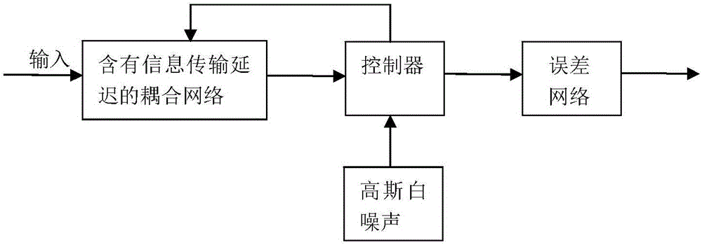
[0006] The technical problem to be solved by the present invention is to overcome the shortcomings of the above-mentioned complex network synchronization, and provide a method for random lag synchronization between coupling networks in a noisy environment with simple methods, low energy consumption for network operation, and easy application

Method used


Image

  • Method for random lag synchronization between coupling networks in noisy environment
  • Method for random lag synchronization between coupling networks in noisy environment
  • Method for random lag synchronization between coupling networks in noisy environment

Examples


Embodiment 1

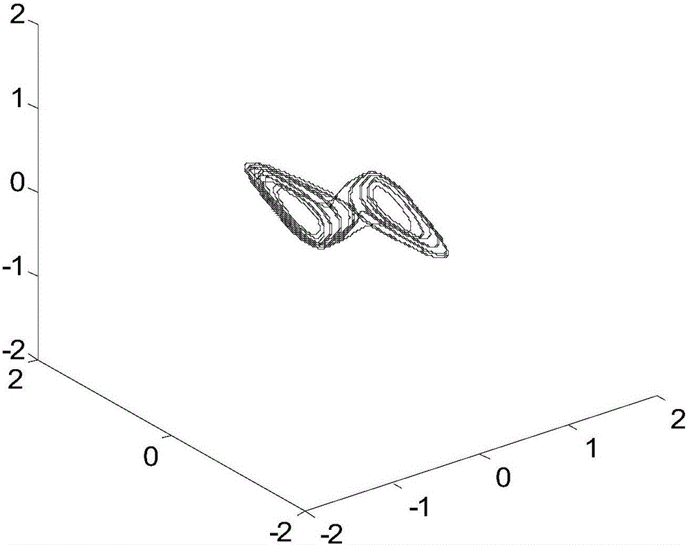
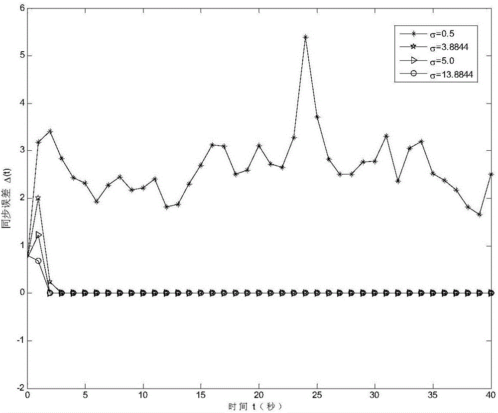
[0050] Taking the number N of network nodes as 15, the node dimension n in the network as 3, and the nodes in the network as cellular neural networks as examples, the method steps of random lag synchronization between coupling networks under noise environment are as follows:

[0051] (1) The coupling network with information transmission delay is:

[0052]

[0053]

[0054] where: t∈R + represents a continuous time variable, x i (t)=(x i1 (t), x i2 (t), x i3 (t)) T ∈ R 3 is the 3D state variable of the i-th node of network 1 at time t, y i (t)=(y i1 (t),y i2 (t),y i3 (t)) T ∈ R 3 is the 3D state variable of the i-th node in network 2 at time t, x i (t-τ)∈R 3 is the 3-dimensional state variable of the i-th node of network 1 at time t behind τ, and τ is the time delay when the information of network 1 is transmitted to network 2, which is used to describe the spatial distance between networks and the information caused by congestion problems Transmission dela...

Embodiment 2

[0088] The number of network nodes N is 15, the dimension n of nodes in the network is 3, and the number of nodes in the network is Taking the vibrator as an example, the method steps of random lag synchronization between coupling networks in a noisy environment are as follows:

[0089] (1) The coupling network with information transmission delay is:

[0090]

[0091]

[0092] where: t∈R + represents a continuous time variable, x i (t)=(x i1 (t), x i2 (t), x i3 (t)) T ∈ R 3 is the 3D state variable of the i-th node of network 1 at time t, y i (t)=(y i1 (t),y i2 (t),y i3 (t)) T ∈ R 3 is the 3D state variable of the i-th node in network 2 at time t, x i (t-τ)∈R 3 is the 3-dimensional state variable of the i-th node of network 1 at time t behind τ, and τ is the time delay when the information of network 1 is transmitted to network 2, which is used to describe the spatial distance between networks and the information caused by congestion problems Transmission...


PUM


Abstract

The invention relates to a method for random lag synchronization between coupling networks in a noisy environment. The method comprises the steps of establishing coupling networks containing information transmission delay, constructing a controller in the noisy environment and determining an error network. According to the method provided by the invention, a linear time lag feedback controller is designed based on a white noise feedback gain, so the random lag synchronization between unidirectional coupling networks in the noisy environment is realized. Compared with the control method that is relatively complex and is not easy to realize in complex network synchronization research, the control method is practical, simple and convenient, the unavoidable noise in the real environment is fully used, and the operation energy consumption of the network is reduced.

Description

technical field [0001] The invention belongs to complex network synchronization technology, in particular to a method for random lag synchronization between coupling networks in a noise environment. Background technique [0002] The chaotic system is extremely sensitive to the initial conditions, and a small change in the initial conditions will cause its dynamic evolution behavior to vary widely. "A butterfly flapping its wings occasionally in the Brazilian jungle may cause a tornado in Texas." This famous butterfly effect is a true portrayal of chaotic signals sensitive to initial conditions and long-term unpredictability. In addition, chaotic signals also have the characteristics of wide frequency spectrum and noise-like characteristics. These characteristics of chaotic signals made people think that chaos is uncontrollable. In the early 1990s, chaos synchronization control was proposed one after another, which subverted the long-standing traditional idea of ​​"chaos is...

Claims


Application Information

Patent Timeline
Patent Type & Authority Applications(China)
IPC IPC(8): H04L7/00H04L12/24
CPCH04L41/145H04L7/0033
Inventor 杨晓丽张丽
Owner SHAANXI NORMAL UNIV
Learn More