Striking unit and method for material processing by the use of high kinetic energy

A material processing and kinetic energy technology, applied in metal processing equipment, power hammers, manufacturing tools, etc., can solve the problems of long adjustment time, cannot be adjusted fast enough, and takes too long adjustment time to achieve fast and efficient pressure Reduced, faster emptying of the drive chamber, lessening the effect of pressure peaks

Active Publication Date: 2017-02-22
CELL IMPACT
View PDF5 Cites 2 Cited by
  • Summary
  • Abstract
  • Description
  • Claims
  • Application Information

AI Technical Summary

Problems solved by technology

With hydraulics, it is technically possible, but most valves on the market have to take too long to adjust to be able to use shorter adjustment times that may be required, usually within 20 milliseconds
Regarding spring machines, it is quite obvious that it is somewhat difficult to form a mechanical device that resolves the spring bias within a few millisecon

Method used


Image

  • Striking unit and method for material processing by the use of high kinetic energy
  • Striking unit and method for material processing by the use of high kinetic energy
  • Striking unit and method for material processing by the use of high kinetic energy

Examples


Embodiment Construction

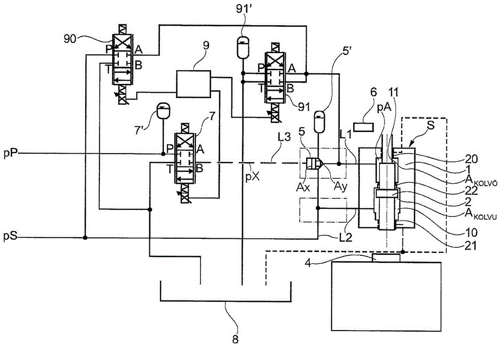
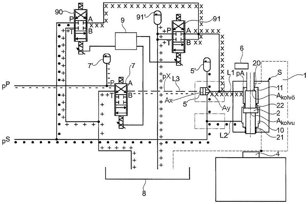
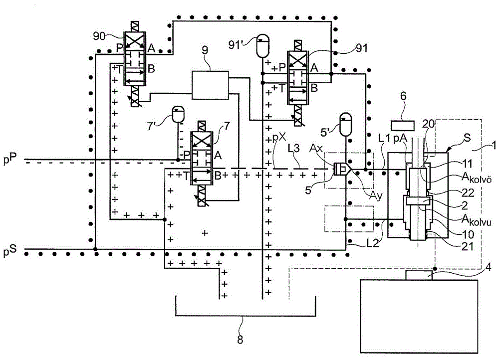
[0023] figure 1 A basic hydraulic diagram is shown for a percussion unit S in a preferred embodiment of the invention, where no crossing conduits of points are not in communication. The figures represent a percussion unit S comprising a cylindrical housing 1 housing a straight-through working plunger 2 . Preferably, the plunger 2 is journaled at its two ends with a first bearing 20 and a second bearing 21 . There is also a third bearing 22 in the middle of the plunger, indicating that two chambers are formed, the driving chamber 11 and the second chamber 10 . Plunger 2 is designed to transfer high kinetic energy to the blank / tool ​​for high speed machining. The drive chamber 11 is connected via a first conduit L1 to the valve member 5, a pressure controlled on / off valve, preferably a cartridge valve. The cartridge valve 5 is connected to the pilot pressure pP via a line L3 , via a valve, preferably via a pilot valve 7 . The term pilot valve refers to a certain type of valv...


PUM


Abstract

The present invention relates to a method at the material processing by the use of high kinetic energy, comprising a plunger (2) which is driven from a start position by a hydraulic system pressure (pS) by means of a drive chamber (1 1) in order, by only one stroke, to transfer high kinetic energy to a blank/tool (4) to be processed, whereafter there is a risk that a rebound of the plunger (2) will occur, and the method comprises that a step is taken in connection with said stroke performed, which step prevents said plunger (2) from making a rebound with an essential content of kinetic energy in order to avoid negative effects as a result of a rebound, whereafter the plunger (2) is returned to said start position by means of a second chamber (10), wherein said step comprises that a valve means (5) closes the driving connection between the system pressure (pS) and the plunger (2), wherein said step comprises that said valve means (5) is controlled by a pilot valve (7) controlling the entire striking progress, and that said second chamber (10) is pressurized with the system pressure (pS) during the entire striking progress.

Description

technical field [0001] The invention relates to an impact unit for a method of material processing by using high kinetic energy, comprising a plunger for transferring high kinetic energy to a blank / tool ​​to be processed, connected to a system arranged to drive said plunger a drive chamber for pressure, valve means arranged to control flow to said drive chamber, and a control system for regulating said valve means, wherein said control system is directly or indirectly connected to a sensor through which said valve means Controlled by said plunger in association with a first impact, so as to reduce or break off the force on the plunger, thereby preventing additional subsequent impacts with a substantial portion of kinetic energy, and to a method wherein said performed The impact is associated with a step which prevents the plunger from rebounding with a major part of the kinetic energy in order to avoid negative effects due to the rebound. Background technique [0002] In hi...

Claims


Application Information

Patent Timeline
IPC IPC(8): B21J7/46B21J7/28
CPCB21J9/12B21J9/20B21J13/02B21J13/06B30B15/16B21J7/28B21J7/46
Inventor 安德斯·伊瓦尔松埃里卡·亨里克森阿莱姆·布尔约巴西克
Owner CELL IMPACT
Why Eureka
Try Eureka