
Centring sleeve for bearing and centring a shaft end

A centering sleeve and centering shaft technology, applied in the field of centering sleeves, can solve problems such as high manufacturing cost, affecting manufacturing cost, and complexity, and achieve the effects of low manufacturing cost, sufficient sealing effect, and firm shape fit

Active Publication Date: 2017-02-22
VIBRACOUSTIC SE
View PDF7 Cites 1 Cited by
  • Summary
  • Abstract
  • Description
  • Claims
  • Application Information

AI Technical Summary

Problems solved by technology

However, such solutions are complex and thus expensive to manufacture
In addition, adhesives are used in the disclosed centering sleeves for joining the elastic elements to the outer and inner bushings, which additionally negatively affects the manufacturing costs

Method used


Image

  • Centring sleeve for bearing and centring a shaft end
  • Centring sleeve for bearing and centring a shaft end
  • Centring sleeve for bearing and centring a shaft end

Examples


Embodiment Construction

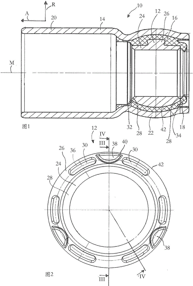
[0028] FIG. 1 shows a cross-sectional view of a centering sleeve 10 according to the invention for positioning and centering a shaft end (not shown).

[0029] The centering sleeve 10 has an inner bushing 12 and an outer bushing 14 surrounding the inner bushing 12 , wherein an elastic part 16 made of elastomer is arranged between the two bushings 12 , 14 . The elastic part 16 has a sealing lip 18 which protrudes from the elastic part 16 in the radial direction R in the direction of the central axis M of the centering sleeve 10 . The sealing lip 18 serves to seal the centering sleeve 10 in such a way that it bears against a shaft end, not shown, which is inserted into the inner sleeve 12 .

[0030] The outer sleeve is designed with an approximately cylindrical connecting section 20 and an adjoining spherical receiving section 22 . The inner sleeve 12 and the spring element 16 are placed or inserted in the receiving section 22 .

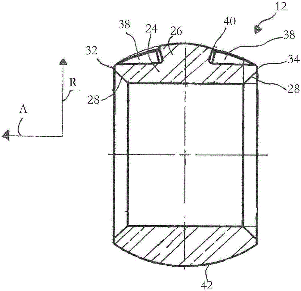
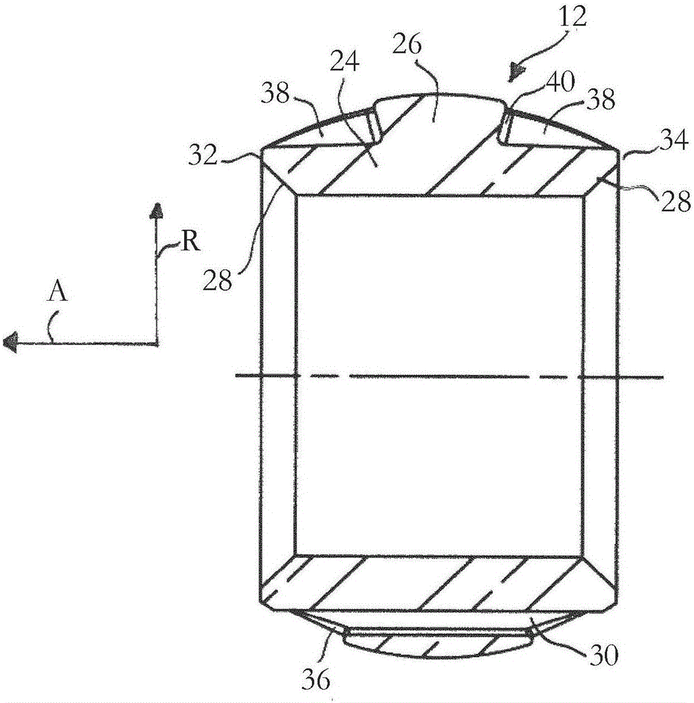
[0031] Especially as shown in Figure 2 to Fig...


PUM


Abstract

The invention relates to a centring sleeve (10) for bearing and centring a shaft end, comprising an inner bushing (12) and an outer bushing (14) that surrounds the inner bushing (12), wherein a spring element (16) is arranged between the inner bushing (12) and the outer bushing (14), said spring element (16) being provided with a sealing lip (18). According to the invention, in order to prevent a lifting of the sealing lip (18) in the case of high cardanic angles, the inner bushing (12) is provided with through openings (30) through which the elastomer passes, in order to create an interlocking connection between the spring element (16) and the inner bushing (12).

Description

technical field [0001] The invention relates to a centering sleeve for supporting and centering a shaft end, which has an inner bush and an outer bush surrounding the inner bush, wherein between the inner bush and the outer bush there is a The elastic member, and the elastic member has a sealing lip. Background technique [0002] Centering sleeves of the aforementioned type are used to center and position shaft ends. To this end, accurate concentricity between the outer bushing and the inner bushing is required. In addition, precise positioning requires high radial rigidity, since otherwise there is a risk of shaft displacement. It is also required that the centering sleeve has a low cardan stiffness in order to compensate for the tilting movement of the two shaft ends. [0003] A centering sleeve is known from DE 10 2005 029 741 A1, which is associated with the joint disc. The centering sleeve has an inner bush and an outer bush, and a spherical elastic part made of ela...

Claims


Application Information

Patent Timeline
IPC IPC(8): F16D3/76F16D21/06F16D13/58
CPCF16D3/76F16D13/58F16D21/06F16C11/0671F16F1/3732
Inventor T·阿姆布拉斯特F·格茨M·埃德曼
Owner VIBRACOUSTIC SE
Learn More