Blind rivet element

A blind rivet, component technology, applied in the direction of rivets, screws, connecting components, etc., can solve problems such as small electrical conductivity

Active Publication Date: 2017-03-01
PROFIL VERBINDUNGSTECHN
View PDF5 Cites 3 Cited by
  • Summary
  • Abstract
  • Description
  • Claims
  • Application Information

AI Technical Summary

Problems solved by technology

This has a problem in that the workpiece especially often has a protective coating, which has no or only relatively little electrical conductivity, and which therefore prevents an effective electrical connection between the workpiece and the blind rivet element

Method used


Image

  • Blind rivet element
  • Blind rivet element
  • Blind rivet element

Examples


Embodiment Construction

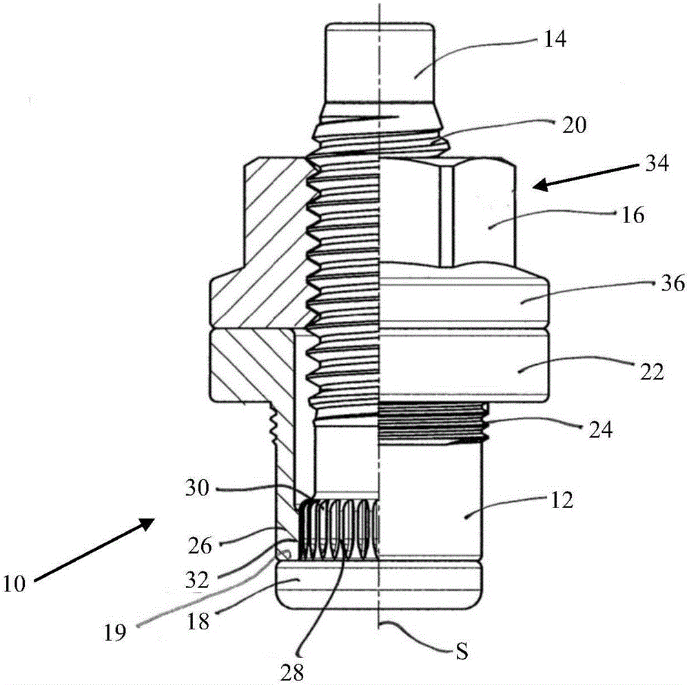
[0056] figure 1 A rotationally symmetrical blind rivet element 10 is shown, comprising a sleeve body 12 , a bolt 14 passing through the sleeve body 12 and a nut 16 . The screw element 14 has a screw head 18 , on whose shoulder 19 the sleeve body 12 is seated. The bolt member 14 also has a thread 20 that cooperates with the internal thread of the nut 16 , that is, the nut 16 is screwed onto the bolt member 14 in the area of ​​the thread 20 .

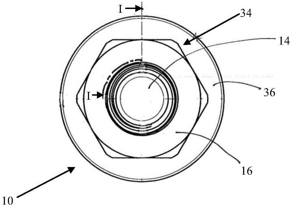
[0057] figure 1 The view of is divided into a left side sectional view and a right side side view with respect to the axis of symmetry S. With respect to the section plane I of the left sectional view at figure 2 shown in . At this point it should be noted that the sectional plane I extends partly straight through the sleeve body 12 and the nut 16 . The cutting plane I also extends along the outer periphery of the bolt member 14 in a curvilinear manner, so that the bolt member 14 is figure 1 Effectively shown as a side view in the ...


PUM


Abstract

A blind rivet element for fastening to a workpiece which has a particularly preformed hole comprising a sleeve body and a bolt element guided through the sleeve body, the blind rivet element being insertable into the hole of the workpiece and the sleeve body being deformable in sections relative to the sleeve body by an axial movement of the bolt element to fasten the blind rivet member to the workpiece. The sleeve body has at least one contact portion which is arranged and configured such that the contact portion cuts into a wall of the hole and / or a region around the hole and / or a deformation of the wall of the hole and / or the area around the hole in particular in order to make an electrical contact between the workpiece and the blind rivet element.

Description

technical field [0001] The invention relates to a blind rivet element for fixing to a workpiece, wherein the blind rivet element includes a sleeve body and a bolt piece passing through the sleeve body. The blind rivet element is generally first guided into the bore of the workpiece. Then, by axial movement of the bolt member relative to the sleeve body, the sleeve body is partially deformed to secure the blind rivet element to the workpiece. Background technique [0002] Such blind rivet elements are also known as mandrel rivets and are frequently used when a reliable and permanent connection is to be established with a workpiece which is only accessible from the outside, that is to say from one side, such as closed hollow bodies . [0003] In an exemplary application, a blind rivet element is secured to a fuel tank to provide a ground connection, ie, an electrical ground connection for the fuel tank. There is also a challenge in this regard, establishing a reliable elect...

Claims


Application Information

Patent Timeline
Patent Type & Authority Applications(China)
IPC IPC(8): F16B19/04F16B5/04
CPCF16B5/04F16B19/04F16B19/1045H01R4/06H01R4/64B21J15/043F16B19/1054F16B37/00
Inventor 奥利弗·迪尔安德里亚斯·朗巴克
Owner PROFIL VERBINDUNGSTECHN
Why Eureka
Try Eureka