Axial air-gap rotary electric machine

一种旋转电机、轴向间隙的技术,应用在带有静止电枢和旋转磁体的同步电动机、电气元件、机电装置等方向,能够解决成本增加、生产效率恶化、间隙尺寸减小等问题,达到成本降低的效果

Active Publication Date: 2017-03-01
HITACHI IND EQUIP SYST CO LTD
View PDF5 Cites 5 Cited by
  • Summary
  • Abstract
  • Description
  • Claims
  • Application Information

AI Technical Summary

Problems solved by technology

On the other hand, if the density of the core or coil is increased, there is a risk of deterioration in production efficiency or increase in cost due to the reduction in the gap size of each part

Method used


Image

  • Axial air-gap rotary electric machine
  • Axial air-gap rotary electric machine
  • Axial air-gap rotary electric machine

Examples


no. 1 approach

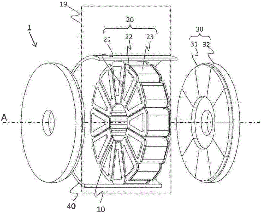
[0031] Hereinafter, the form for implementing this invention is demonstrated using drawing. figure 1 , schematically shows the armature structure of the dual-rotor axial gap permanent magnet synchronous motor 1 (hereinafter sometimes referred to as "motor 1") according to the first embodiment of the present invention.

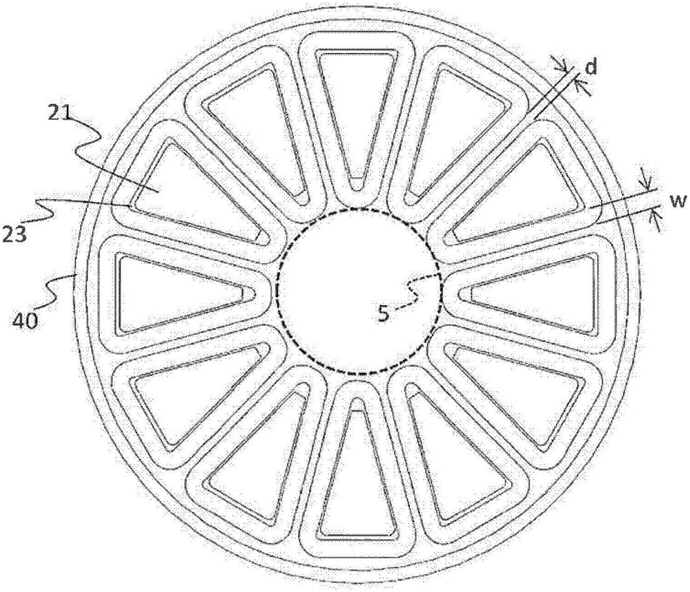
[0032] The motor 1 includes an annular stator 19 along the inner periphery of a housing 40 and two disk-shaped rotors 30 arranged to sandwich the stator 19 in the axial direction of the rotating shaft. The end surface of the stator 19 and the circular plane of the rotor 30 face each other with a predetermined gap in the radial direction of the rotation axis. A rotating shaft (not shown) connected to the center of the rotor 19 penetrates through the gap of the inner cylinder formed at the center of the stator 20 and is connected to the rotor 19 disposed on the opposite side with the stator 20 interposed therebetween. Both ends of the rotary shaft are rotatably ...

no. 2 approach

[0057] One of the features of the motor 1 of the second embodiment is that the first region 10 of the first embodiment is used as a region for accommodating the connecting wires 51 drawn from the core members 20 .

[0058] Figure 7 It is a perspective view showing the stator 19 of the motor 1 . In addition, resin for molding the stator 19 is omitted for simplicity. In addition, for the same parts as those of the first embodiment, the same symbols are used and descriptions thereof are omitted.

[0059] The connection wire 51 drawn out from the magnetic core member 51 is arranged in the first region 10 formed on the one output shaft side. The connecting wires 51 are gathered to the magnetic core member 20 closest to the terminal box to form a connecting wire group 50 .

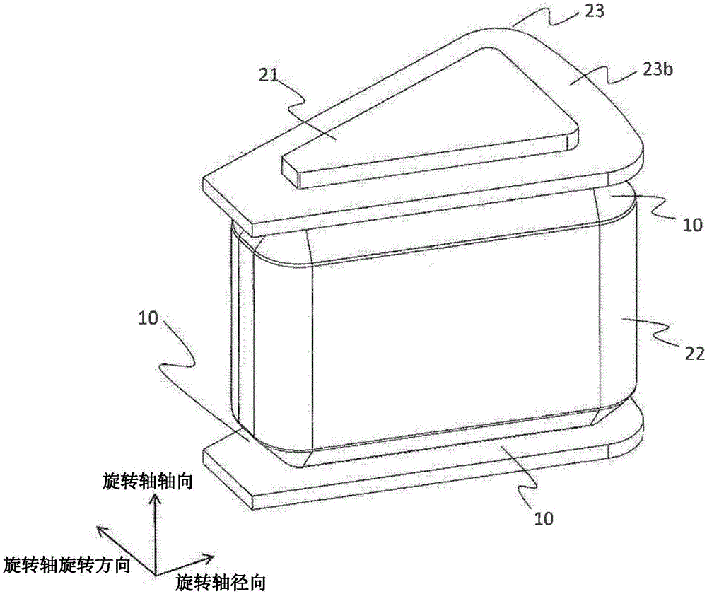
[0060] In the case where the coil 22 is wound around the entire area between the flange portions 23b, it is conceivable to place the connecting wires near the surface of the flange portion 23b on the rotor 3...

no. 3 approach

[0064] One of the features of the motor 1 of the third embodiment is that the first region 10 formed on the inner peripheral side of the casing 40 from the rotation axis direction is used as a wiring arrangement region.

[0065] Figure 8 It is a sectional perspective view showing the stator 19 of the third embodiment. In addition, for the same parts as those of the first embodiment, the same symbols are used and descriptions thereof are omitted.

[0066] The motor 1 of the third embodiment has a cylindrical first conductive member 61 on the rotation axis side of the stator 19 . The first conductive member 61 is formed of a thin plate bent into a cylindrical shape, and the rotation shaft penetrates through the inner cylinder side. The lead wire 62 is connected to a part of the outside of the first conductive member 61 . The lead wire 61 passes through the first region 10 formed on the inner peripheral side of the case 40 from the rotation axis, and the other end is electric...


PUM


Abstract

The present invention provides an axial air-gap rotary electric machine (1) that is provided with: a stator (19) in which a plurality of core members (20), which have an iron core (21), a coil (22) that is wound around the outer periphery of the iron core, and a bobbin (23) that is disposed between the iron core and the coil, are arranged in a circular shape centred around a rotational axis (A); and at least one rotor (30) that faces an end surface of the iron core with a prescribed air gap therebetween in the radial direction of the rotational axis. Therein, the bobbin (23) has a cylinder portion (23a) into which the iron core is inserted, and a flange portion (23b) that extends for a prescribed length around the outer periphery of the cylinder portion (23a) and in a vertical direction, and the coil (22) is wound around the outer periphery of the cylinder portion (23a) by regular winding, and is formed by a sequence of layers wherein the number of turns for each layer wound further to the outside than the layer that is wound so as to be in contact with the flange portion (23b) is at least one less than the number of turns in the adjoining inner layer.

Description

technical field [0001] The present invention relates to an axial gap type rotating electrical machine, and relates to an axial gap type rotating electrical machine in which a coil is wound on a bobbin. Background technique [0002] In pursuit of miniaturization and high efficiency of rotating electrical machines, axial gap type rotating electrical machines are attracting attention. The rotary electric machine has a structure in which a disc-shaped rotor and a cylindrical stator face each other in the axial direction of the rotating shaft. Since the torque-generating clearance surface increases approximately in proportion to the square of the diameter, it is particularly effective for downsizing and improving the efficiency of a thin rotating electric machine. [0003] The stator of the axial gap type rotating electrical machine includes a plurality of iron cores arranged along the inner circumference of a case, and coils wound around the iron cores via an insulating member....

Claims


Application Information

Patent Timeline
Patent Type & Authority Applications(China)
IPC IPC(8): H02K21/24H02K3/46
CPCH02K3/46H02K3/18H02K1/2795H02K21/24H02K3/325
Inventor 床井博洋北岛大辅川越友则山崎克之酒井亨高桥秀一铃木利文岩崎则久正木良三榎本裕治
Owner HITACHI IND EQUIP SYST CO LTD
Why Eureka
Try Eureka