Double-bent-welding-wire narrow-gap gas metal arc welding torch

A technology of melting electrode gas and narrow gap, which is applied to the characteristics of electrodes, welding equipment, arc welding equipment, etc., can solve the problems of increasing the heat input of the side wall, the side wall is not fused, and the actual effect is yet to be verified, so as to improve the utilization rate, Compact structure and good adaptability of groove width

Inactive Publication Date: 2017-03-08
GUANGDONG PROVINCIAL INST OF WELDING TECH GUANGDONG PROVINCIAL ACADEMY OF UKRAINE
View PDF9 Cites 4 Cited by
  • Summary
  • Abstract
  • Description
  • Claims
  • Application Information

AI Technical Summary

Problems solved by technology

However, in the actual welding process, narrow gap welding is prone to side wall non-fusion defects. The key to solving side wall non-fusion is to improve the arc heating area and increase the heat input of the side wall
In response to this problem, welding workers at home and abroad have developed a variety of narrow-gap welding methods such as rotating arc narrow-gap welding, oscillating arc narrow-gap welding, double-wire narrow-gap welding, and curved wire narrow-gap welding, but the actual effect has yet to be verified.

Method used


Image

  • Double-bent-welding-wire narrow-gap gas metal arc welding torch
  • Double-bent-welding-wire narrow-gap gas metal arc welding torch
  • Double-bent-welding-wire narrow-gap gas metal arc welding torch

Examples


Embodiment 1

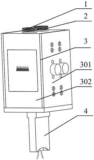
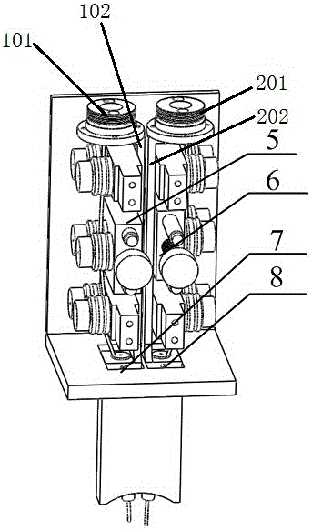
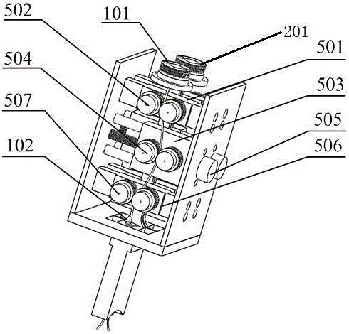
[0042] Such as Figure 1-8 As shown, a double-bent welding wire narrow-gap MIG shielded welding torch includes a front conductive mechanism 1, a rear conductive mechanism 2, a welding torch box 3, a plug-in nozzle 4, a front wire bending mechanism 5, and a rear wire bending mechanism 6. The front conductive mechanism 1, the rear conductive mechanism 2, the front wire bending mechanism 5 and the rear wire bending mechanism 6 are located in the torch box 3, and the front conductive mechanism 1 and the rear conductive mechanism 2 are arranged in parallel; the front The conductive mechanism 1 includes a front conductive connector 101, a front conductive plate 102, a front conductive rod 103, and a front conductive tip 104. The upper end of the front conductive plate 102 is connected with the front cable connector 101, and the lower end is connected with the front conductive rod 103. The mouth 104 is connected to the lower end of the front conductive rod 103; the rear conductive me...


PUM


Abstract

The invention relates to a welding technology, in particular to a double-bent-welding-wire narrow-gap gas metal arc welding torch comprising a front electric conduction mechanism 1, a rear electric conduction mechanism 2, a welding torch box 3, an inserted type spray nozzle 4, a front wire bending mechanism 5 and a rear wire bending mechanism 6. The front electric conduction mechanism 1, the rear electric conduction mechanism 2, the front wire bending mechanism 5 and the rear wire bending mechanism 6 are located in the welding torque box 3. The front electric conduction mechanism 1 and the rear electric conduction mechanism 2 are arranged in parallel. The double-bent-welding-wire narrow-gap gas metal arc welding torch is characterized in that the front electric conduction mechanism 1 comprises a front electric conduction connector 101, a front electric conduction plate 102, a front electric conduction rod 103 and a front electric conduction nozzle 104. The upper end of the front electric conduction plate 102 is connected with the front electric conduction connector 101, and the lower end of the front electric conduction plate 102 is connected with the front electric conduction rod 103. The front electric conduction nozzle 104 is connected to the lower end of the front electric conduction rod 103. The rear electric conduction mechanism 2 is similar to the front electric conduction mechanism.

Description

technical field [0001] The invention relates to welding technology, and more specifically relates to a double-curved welding wire narrow-gap MIG shielded welding torch. Background technique [0002] Narrow-gap MIG welding reduces the cross-sectional size of the weld due to the use of small-sized I-shaped or small-angle V-shaped grooves. Compared with traditional welding methods, it has high welding efficiency, less filler material, and low welding heat input. There are many advantages such as welding deformation and small residual stress after welding. However, in the actual welding process, narrow gap welding is prone to side wall non-fusion defects. The key to solving side wall non-fusion is to improve the arc heating area and increase the heat input of the side wall. In response to this problem, welding workers at home and abroad have developed a variety of narrow-gap welding methods such as rotating arc narrow-gap welding, oscillating arc narrow-gap welding, double-wire...

Claims


Application Information

Patent Timeline
Patent Type & Authority Applications(China)
IPC IPC(8): B23K9/28B23K9/173
CPCB23K9/28B23K9/173
Inventor 徐望辉易耀勇李双张宇鹏房卫萍余陈罗子艺韩善果蔡得涛高雯雯陈永城
Owner GUANGDONG PROVINCIAL INST OF WELDING TECH GUANGDONG PROVINCIAL ACADEMY OF UKRAINE
Why Eureka
Try Eureka