Vehicle Speed Control System

A vehicle speed control and control unit technology, applied in the system field, can solve the problem of not considering the speed limit of vehicles and roads

Inactive Publication Date: 2017-03-08
TOYOTA JIDOSHA KK
View PDF6 Cites 12 Cited by
  • Summary
  • Abstract
  • Description
  • Claims
  • Application Information

AI Technical Summary

Problems solved by technology

[0003] However, according to the prior art as described above, when the allowable speed is calculated, the speed limit of the road on which the vehicle is traveling is not considered; therefore, the vehicle may enter a curve at a speed exceeding the speed limit

Method used


Image

  • Vehicle Speed Control System
  • Vehicle Speed Control System
  • Vehicle Speed Control System

Examples


no. 1 example

[0035] In the following, reference will be made to Figure 1 to Figure 5 A vehicle speed control system according to a first embodiment of the present invention will be described.

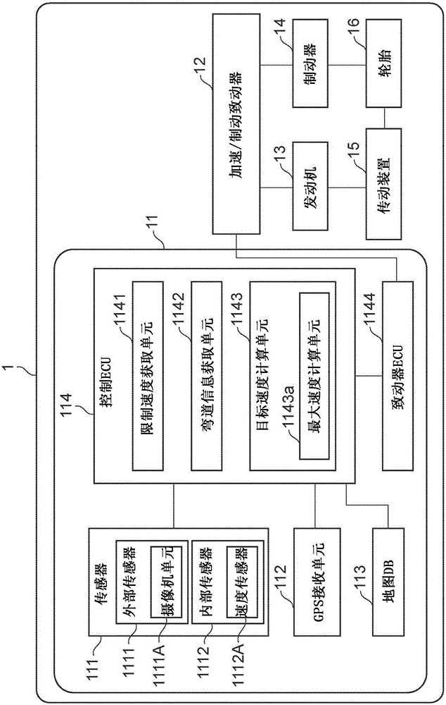
[0036] will refer to figure 1 An example of the vehicle speed control system of the first embodiment will be described. figure 1 is a block diagram showing one example of the configuration of a vehicle on which the vehicle speed control system of the first embodiment is mounted.

[0037] Such as figure 1 As shown, vehicle 1 includes vehicle speed control system 11 , acceleration / braking actuator 12 , engine 13 , brakes 14 , transmission 15 and tires 16 .

[0038] In order to calculate various signals to be output to the acceleration / brake actuator 12, the vehicle speed control system 11 includes: a sensor 11, a GPS (Global Positioning System) receiving unit 112, a map DB (database) 113, a control ECU (Electronic Control Unit ) 114 and actuator ECU1144.

[0039] The sensor 111 is a detecting de...

no. 2 example

[0089] The following will refer to Figure 6 to Figure 8 A vehicle speed control system according to a second embodiment of the invention is described. Although a part of the operation differs between the second embodiment and the first implementation as described above, there are many similar or identical parts in the rest of the operation. Therefore, only portions of the second embodiment that are different from the first embodiment already described above will be described in detail, and descriptions of overlapping portions will be appropriately omitted.

[0090] An example of the vehicle speed control system of the second embodiment will be described. Figure 6 is a block diagram showing one example of the configuration of a vehicle on which the vehicle speed control system of the second embodiment is mounted.

[0091] Figure 6 The illustrated vehicle speed control system 21 according to the second embodiment is installed on the vehicle 2 and is connected with figure ...


PUM


Abstract

A vehicle speed control system includes a speed limit obtaining unit that obtains a speed limit for a road in front of a vehicle, a curve information obtaining unit that detects a curve on the road, and calculates a distance from a current position of the vehicle to a start position of the curve and a radius of curvature of the curve, a calculating unit that calculates a first maximum speed at which the vehicle does not deviate from a traveling lane on the curve, based on the radius of curvature, and a control unit that controls the vehicle such that a speed of the vehicle at the start position becomes substantially equal to the first maximum speed, when the first maximum speed does not exceed the speed limit.

Description

technical field [0001] The invention relates to a system for driving support, for example, when a vehicle is traveling along a curve, and in particular to a system for controlling the vehicle speed before the vehicle enters a curve. Background technique [0002] As an example of this type of system, there has been proposed a system that obtains the radius of curvature about the curve, calculates the allowable speed that allows the vehicle to travel along the curve from the radius of curvature, and when the speed of the vehicle exceeds When the speed is allowed, a warning is given to the driver of the vehicle (see Japanese Patent Application Laid-Open No. 07-266919 (JP 07-266919 A)). [0003] However, according to the prior art as described above, when calculating the allowable speed, the speed limit of the road on which the vehicle is traveling is not considered; therefore, the vehicle may enter a curve at a speed exceeding the speed limit. Contents of the invention [00...

Claims


Application Information

Patent Timeline
Patent Type & Authority Applications(China)
IPC IPC(8): B60W30/14
CPCB60W30/146B60W2720/10B60W2552/30B60W2555/60B60W30/143B60W2420/42
Inventor 及川善贵田中信莫拉莱斯寺冈埃德加芳男
Owner TOYOTA JIDOSHA KK
Why Eureka
Try Eureka