Engine system having coolant control valve

An engine system, coolant valve technology, applied in the control of coolant flow, engine components, cooling of the engine, etc., can solve problems such as prolonged standardization of heater operation time, increased fuel consumption, and cold passengers or drivers.

Active Publication Date: 2017-03-08
HYUNDAI MOTOR CO LTD
View PDF7 Cites 8 Cited by
  • Summary
  • Abstract
  • Description
  • Claims
  • Application Information

AI Technical Summary

Problems solved by technology

Therefore, the frictional force increases, the fuel consumption increases, the temperature of the exhaust gas gradually rises, and thus, the activation time of the catalyst prolongs, and thus, the quality of the exhaust gas may deteriorate
In addition, the operating normalization time of the heater is prolonged, so that passengers or the driver may feel cold
[0006] When the coolant temperature of the engine is too high, knocking occurs, and the ignition timing needs to be adjusted to suppress the occurrence of knocking, resulting in poor operation
In addition, when the temperature of the lubricant is excessively high, the lubricating performance may deteriorate

Method used


Image

  • Engine system having coolant control valve
  • Engine system having coolant control valve
  • Engine system having coolant control valve

Examples


Embodiment Construction

[0033] An exemplary embodiment of the present invention will be described in detail below with reference to the accompanying drawings.

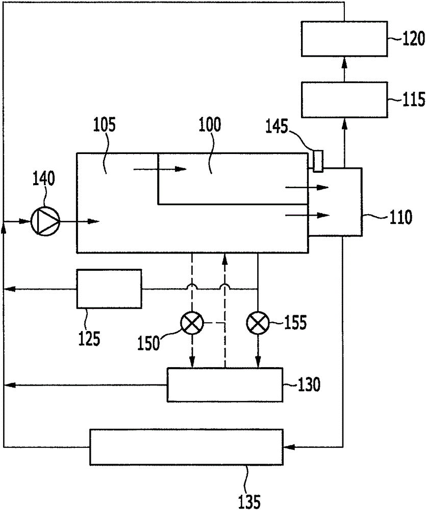
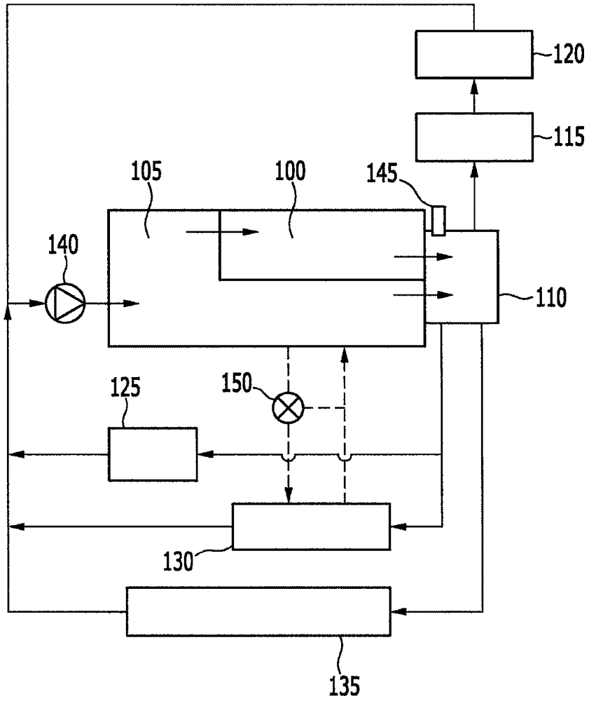
[0034] figure 1 is a schematic diagram showing typical coolant flow in an engine system with a conventional coolant control valve unit.

[0035] refer to figure 1 , the engine system includes a cylinder head 100, a cylinder block 105, a coolant pump 140, a high-pressure exhaust gas recirculation (EGR) valve 125, a bypass valve 150, a thermostat (thermostat) 155, an oil cooler 130, a radiator 135, The coolant controls the valve unit 110 , the temperature sensor 145 , the low pressure EGR cooler 115 and the heater 120 .

[0036] The cylinder head 100 is arranged on the cylinder block 105 . A combustion chamber in which a piston is arranged is formed in the cylinder block 105 , and an exhaust port and an intake port communicating with the combustion chamber are formed in the cylinder head 100 .

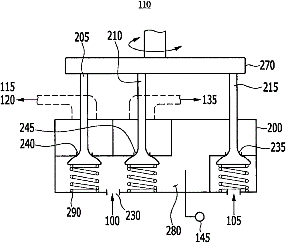
[0037] The coolant control valve unit 110 dis...


PUM


Abstract

An engine system includes a cylinder block and a cylinder head. A coolant control valve unit is engaged with the cylinder head to receive a coolant exhausted from the cylinder block and a coolant exhausted from the cylinder head. The coolant control valve unit controls a coolant to be supplied to a heater, a radiator, and an oil cooler and controls the coolant exhausted from the cylinder block. The coolant control valve unit receives the coolant from the cylinder head, supplies the coolant to the oil cooler, and controls the coolant distributed to the heater and the coolant exhausted from the cylinder block.

Description

[0001] Cross References to Related Applications [0002] This application claims priority from Korean Patent Application No. 10-2015-0119559 filed with the Korean Intellectual Property Office on Aug. 25, 2015, the entire contents of which are incorporated herein by reference. technical field [0003] The present invention relates to an engine system having a coolant control valve unit that improves cooling efficiency and reduces fuel consumption by controlling coolant distribution to a radiator, heater, oil cooler, and the like. Background technique [0004] The engine generates rotational force by burning fuel, and the remaining energy from the combustion of the fuel is discharged as heat energy. Specifically, the coolant absorbs thermal energy while circulating through the engine, heater, radiator, and discharges the absorbed thermal energy to the outside. [0005] When the coolant temperature of the engine is low, the oil viscosity increases. Therefore, the frictional f...

Claims


Application Information

Patent Timeline
Patent Type & Authority Applications(China)
IPC IPC(8): F01P7/14F01P7/16
CPCF01P7/14F01P7/16F01P2007/146F01P7/165F16K31/52416F16K11/165F01P2003/027F01P2060/04F01P2060/08F01P2060/18F01P11/08F01P11/16
Inventor 李勇珪李孝祚姜镐均赵晟文尹硕浚柳炫旭李珍岛
Owner HYUNDAI MOTOR CO LTD
Why Eureka
Try Eureka