Novel turnover device
A flipping device and a new type of technology, applied in the direction of transmission, transmission parts, gear transmission, etc., can solve the problems of unreasonable structural design of the driving mechanism, prone to safety accidents, unstable work, etc. Use safety performance, reasonable structure design effect
- Summary
- Abstract
- Description
- Claims
- Application Information
AI Technical Summary
Problems solved by technology
Method used
Image

Examples
Embodiment 1
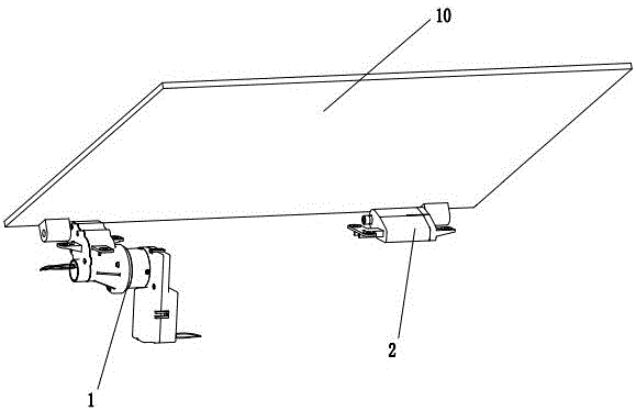
[0021] Embodiment one: as attached Figure 1~3 As shown, the novel flipping device disclosed in this embodiment includes a driving mechanism 1 and a damping mechanism 2, and the driving mechanism 1 and the damping mechanism 2 are connected to the cover plate 10 respectively, and drive the cover plate 10 to flip open and close.
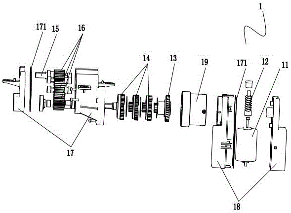
[0022] In this embodiment, the drive mechanism 1 includes a motor 11, a worm 12 connected to the motor 11, a helical gear 13 meshed with the worm 12, a planetary gear set 14, and an output shaft 15 arranged parallel to the cover plate 10; the motor 11 and the worm 12 are all installed in the box body 2 18, and a sealing gasket 171 is provided in the box body 2 18, so as to achieve the effects of waterproof, dustproof and noise reduction; a ring body 19 with a ring gear inside is installed on the outside of the box body 2 18 , The planetary gear set 14 is installed in the ring body 19, and the planetary gears are in multiple groups, and the planetary ge...
Embodiment 2
[0031] Embodiment two: as attached Figure 4-5 As shown, the overall structure of the new turning device disclosed in this embodiment is similar to that in Embodiment 1, except that the structure of the damping mechanism 2' is different.
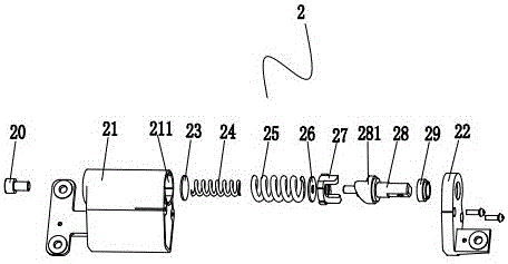
[0032] In this embodiment, the damping mechanism 2' includes the second shell 21' and the second cover 22', the second shell 21' and the second cover 22' are fixedly connected by screws, and a special-shaped cam is horizontally installed in the second shell 21' Shaft 23', the two ends of special-shaped camshaft 23' are respectively connected with bearings 29, one end of special-shaped camshaft 23' protrudes from cover body 22' and is connected with cover plate 10, and the cam 231 of special-shaped camshaft in housing two 21' ’ is vertically provided with a mounting groove below, and a compression spring 24’ is installed in the mounting groove, and a steel ball 25’ is arranged on the upper end of the compression spring 24’. In the initial sta...
PUM
 Abstract
Description
Claims
Application Information