Distributor in falling film evaporator

A technology of falling film evaporator and distributor, which is applied in the direction of evaporator/condenser, fluid circulation arrangement, refrigeration components, etc., can solve the problem of stable operation of chillers that affect the heat transfer efficiency of falling film evaporators, and cannot be completely soaked and exchanged Problems such as heat pipes and unfavorable film boiling heat transfer can be achieved to reduce adverse effects, avoid suction back to liquid, and stabilize air flow

Active Publication Date: 2017-03-08
顿汉布什(中国)工业有限公司
View PDF8 Cites 10 Cited by
  • Summary
  • Abstract
  • Description
  • Claims
  • Application Information

AI Technical Summary

Problems solved by technology

[0004] 2. The bottom of the conventional drip pan is generally equipped with circular holes, square holes or diagonal holes. Because the refrigerant has a certain viscosity, the simple gravity cannot completely overcome the viscous force and drip down smoothly to the heat exchange. On the tube, the outer surface of the heat exchange tube cannot be completely infiltrated, which is not conducive to film boiling heat transfer
[0005] 3. Conventional falling film distributors are generally not equipped with the equalization plate. At the position near the suction port on the top of the falling film evaporator, the air flow is relatively concentrated and the flow rate is relatively fast.
In the process of the falling film distributing refrigerant, near the suction nozzle, because the gas flows upwards and the flow velocity is fast, the refrigerant liquid that drops down is subjected to a large upward force and is carried to the suction port, thereby Liquid back occurs, which seriously affects the heat transfer efficiency of the falling film evaporator and the stable operation of the chiller

Method used


Image

  • Distributor in falling film evaporator
  • Distributor in falling film evaporator
  • Distributor in falling film evaporator

Examples


Embodiment Construction

[0026] The principles and features of the present invention are described below in conjunction with the accompanying drawings, and the examples given are only used to explain the present invention, and are not intended to limit the scope of the present invention.

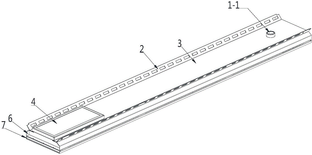
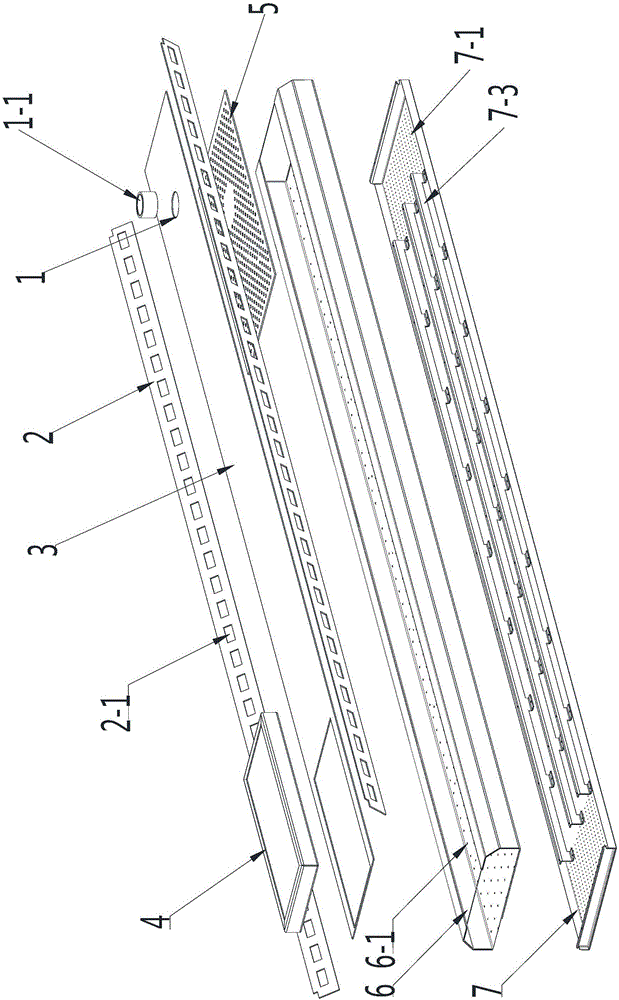
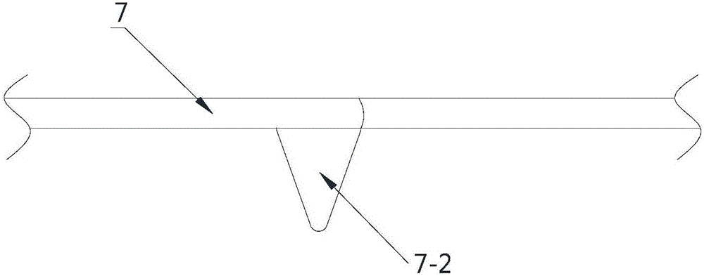
[0027] Such as Figure 1~2 As shown, it includes a cover plate 3, a gas-liquid separation tray 6 and a gravity drip tray 7, and the bottom 7 of the gravity drip tray is uniformly covered with water holes 7-1 and is provided with a plurality of partitions 7-3. The top of the gravity drip tray 7 is connected with the gas-liquid separation tray 6, the bottom plate of the gas-liquid separation tray 6 is evenly distributed with pressure holes 6-1, and the gas-liquid separation tray 6 is fixedly connected with a cover plate 3, The gas-liquid separation disc 6 and the cover plate 3 form a closed gas-liquid separation chamber, and the cover plate 3 is provided with a liquid inlet 1 and a demister 4, because the gas-liquid s...


PUM


Abstract

The invention relates to evaporator accessories in refrigerating equipment, in particular to a distributor in a falling film evaporator. The distributor comprises a cover plate, a gas-liquid separation disc and a gravity drop-leaching disc, wherein water holes are uniformly and densely distributed and a plurality of partition plates are arranged at the bottom of the gravity drop-leaching disc; the gas-liquid separation disc is connected with the top end of the gravity drop-leaching disc; pressure holes are uniformly distributed on a baseplate at the bottom of the gas-liquid separation disc; the cover plate is fixedly connected onto the gas-liquid separation disc; the gas-liquid separation disc and the cover plate are combined to form an enclosed gas-liquid separation cavity; and a liquid inlet and a demister are arranged on the cover plate. The distributor provided by the invention has the following beneficial effects: a gaseous refrigerant in a gas-liquid two-phase refrigerant can be separated out, and liquid drops can be prevented from being entrained by the gaseous refrigerant, thereby achieving uniform and effective gas exhaust; and meanwhile, uniform dropping of a liquid can be guaranteed, thereby reducing the adverse impact of gas flow in an evaporation process.

Description

technical field [0001] The invention relates to evaporator fittings in refrigeration equipment, in particular to a distributor used in falling film evaporators. Background technique [0002] The working principle of the falling film evaporator is: the refrigerant liquid condensed from the condenser expands through the throttling device to form a gas-liquid two-phase refrigerant. Driven by pressure, the gas-liquid two-phase refrigeration The refrigerant enters the distributor at the top of the evaporator and is distributed through multiple stages. Finally, the refrigerant is left from the distribution hole at the bottom of the distributor and drops on the heat exchange tube of the evaporator. From top to bottom, it drips down to the heat exchange tube below, so that the refrigerant evaporates, and the heat is transferred from the medium in the heat exchange tube to the refrigerant, thereby achieving the cooling effect. In the above process, the most critical factor affecting...

Claims


Application Information

Patent Timeline
Patent Type & Authority Applications(China)
IPC IPC(8): F25B39/02F25B41/00F25B41/42
CPCF25B39/028F25B41/00
Inventor 周雷杜国良王发忠
Owner 顿汉布什(中国)工业有限公司
Why Eureka
Try Eureka