Compact-structure type magnetic coupling driving motor

A compact, magnetic coupling technology, applied in structural connections, permanent magnetic clutches/brakes, electrical components, etc., can solve problems such as low efficiency of magnetic field utilization, increasing the axial size of the pump, and limiting the installation space of the magnetic coupling pump. Achieve the effect of compact structure, shortened axial dimension, and meet the needs of flexible connection

Active Publication Date: 2017-03-08
INST OF MACHINERY MFG TECH CHINA ACAD OF ENG PHYSICS
View PDF5 Cites 2 Cited by
  • Summary
  • Abstract
  • Description
  • Claims
  • Application Information

AI Technical Summary

Problems solved by technology

The device has a pump chamber and a motor chamber separated by a partition wall, and the motor chamber is equipped with: a stator, a rotor, and a driving magnet; the pump chamber is equipped with an impeller with a driven magnet. In this device, the drive The magnet and the driven magnet are in the form of radial ring permanent magnets, and its magnetic coupling unit increases the axial dimension of the pump, which limits the installation space of the magnetic coupling pump
At the same time, the permanent magnets of the motor rotor and the permanent magnets for magnetic coupling are arranged separately, and the utilization efficiency of the magnetic field is low

Method used


Image

  • Compact-structure type magnetic coupling driving motor
  • Compact-structure type magnetic coupling driving motor

Examples


Embodiment 1

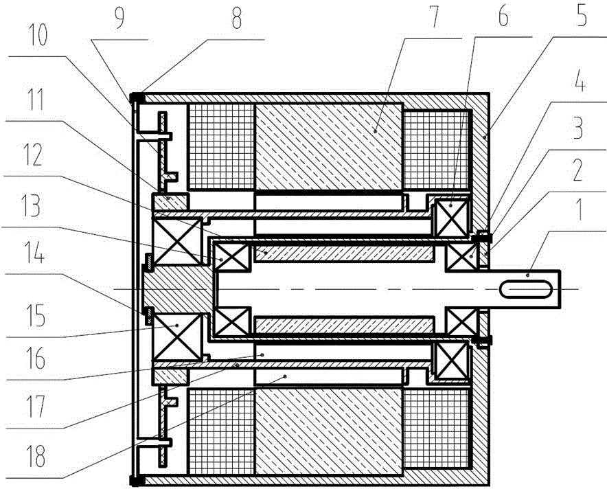
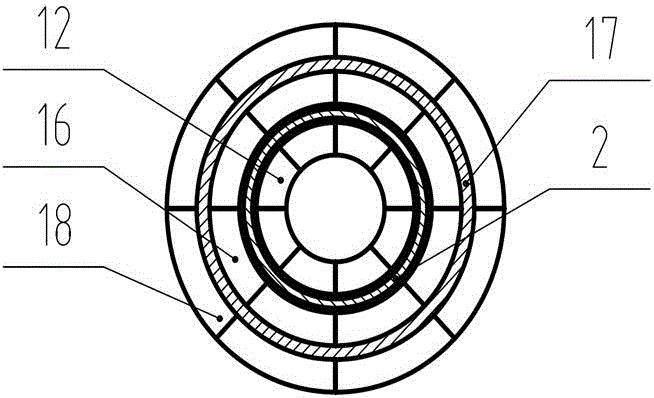
[0029] figure 1 It is a structural schematic diagram of a compact magnetic coupling drive motor of the present invention, figure 2 for figure 1 A schematic diagram of the local structure. figure 2 A schematic diagram of the axial structure of the permanent magnet 12 of the inner shaft, the inner magnet 16 of the inner rotor, and the outer magnet 18 of the inner rotor is shown. exist figure 1 , figure 2 Among them, the compact magnetic coupling motor of the present invention includes a motor housing 5, an inner shaft front end bearing 4, an inner rotor front end bearing 6, a rear end cover 9, an inner shaft rear end bearing 13, a rear end bearing 15 and a The inner stator 7 and the inner rotor 17 in the casing 5, the inner rotor 17 is cylindrical. The connection relationship is that the two ends of the inner rotor 17 are respectively connected to the inner rotor front end bearing 6 and the inner rotor rear end bearing 15, and several inner rotor inner magnets 16 are eve...

Embodiment 2

[0046] The structure of this embodiment is the same as that of Embodiment 1. The difference is that the permanent magnet poles of the inner shaft permanent magnet, the inner rotor inner magnet, and the inner rotor outer magnet are all equal even-numbered poles. In this embodiment, the even-numbered poles are twelve. indivual.


PUM


Abstract

The invention provides a compact-structure type magnetic coupling driving motor. The magnetic coupling driving motor comprises a motor shell, and an inner stator, an inner rotor and an inner rotary shaft positioned in the motor shell, wherein the inner rotor adopts a cylindric shape; the two ends of the inner rotor are connected with an inner rotor front end bearing and an inner rotor back end bearing respectively; inner rotor inner magnets and inner rotor outer magnets are uniformly distributed on the inner and outer side walls of the inner rotor; the inner rotary shaft is arranged in the inner rotor in a sleeving manner; the inner rotary shaft coincides with the axle wire of the inner rotor; the two ends of the inner rotary shaft are connected with an inner rotary shaft front end bearing and an inner rotary shaft back end bearing respectively; inner rotary shaft permanent magnets corresponding to the inner rotor inner magnets of the inner rotor are also fixed on the inner rotary shaft; and the inner rotor and the inner rotary shaft are subjected to physical isolation. The compact-structure type magnetic coupling driving motor has the beneficial effects of capability of satisfying flexible connection requirement, skillful layout, compact structure, high magnetic field efficiency of the permanent magnets, high sealing property, and capability of saving the axial space of the motor.

Description

technical field [0001] The invention belongs to the technical field of magnetic coupling drive motors, and in particular relates to a magnetic coupling drive motor with a compact structure. Background technique [0002] The magnetically coupled motor is a transmission motor that utilizes the same-sex repulsion and opposite-sex attraction of magnets for magnetic field coupling. It can physically isolate the rotor, stator and load of the motor to achieve zero leakage in harsh environments. Generally, a magnetically coupled motor is mainly composed of three basic parts: a copper stator, a permanent magnet rotor, and a magnetic coupling unit. The magnetic coupling motor can realize the physical isolation between the motor parts and the load, flexible connection and prevent the motor from stalling, and avoid the dynamic seal, and the sealing reliability is very high. It has been widely used in the chemical, petroleum, toxic and harmful liquid pipeline transportation industries. ...

Claims


Application Information

Patent Timeline
Patent Type & Authority Applications(China)
IPC IPC(8): H02K49/10H02K11/215
CPCH02K49/102H02K49/106
Inventor 汤金钢陈金明黄姝珂杜东兴雷艳华张新疆徐健
Owner INST OF MACHINERY MFG TECH CHINA ACAD OF ENG PHYSICS
Why Eureka
Try Eureka