Ceramic grouting equipment with automatic feeding function and grouting method

An automatic feeding and grouting technology, which is applied to ceramic molding machines, ceramic molding workshops, auxiliary molding equipment, etc., can solve the problems of easy blockage of pipelines, low labor efficiency, and inability to adjust, so as to improve the quality of green bodies and reduce operations. Strength, the effect of improving the utilization rate

Inactive Publication Date: 2017-03-15
SHISHI TAIRUI PRECISION MACHINERY
View PDF5 Cites 9 Cited by
  • Summary
  • Abstract
  • Description
  • Claims
  • Application Information

AI Technical Summary

Problems solved by technology

This method mainly reduces the labor intensity, but there are also many disadvantages
The more prominent ones are: first, there will be sediment in the slurry tank, which will easily block the pipeline; second, due to the limited height of the tank, the grouting pressure and flow rate are small and cannot be adjusted, and the labor efficiency is still very low; third, a workshop is limited to If one kind o

Method used


Image

  • Ceramic grouting equipment with automatic feeding function and grouting method
  • Ceramic grouting equipment with automatic feeding function and grouting method
  • Ceramic grouting equipment with automatic feeding function and grouting method

Examples


specific Embodiment 1

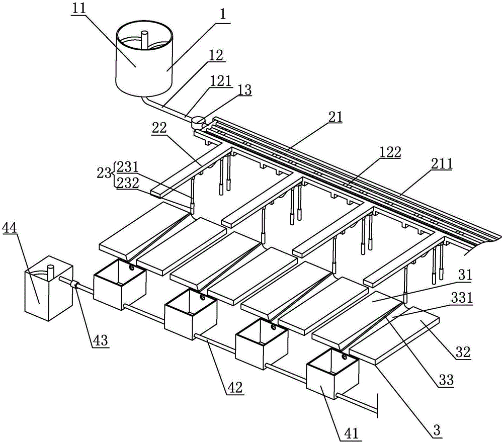
[0028] Specific embodiment one: with reference to figure 1 As shown, automatic feeding ceramic grouting equipment, including feeding system, grouting system, operating platform and waste recycling system;

[0029] The feeding system includes a slurry mixing tank 11, a feeding pipeline 12 and a booster pump 13. The mixing tank 11 is located above the feeding track or the slurry mixing tank 11 is placed on a higher floor. The feeding pipeline 12 includes a main A feed pipeline 121 and a plurality of distribution pipelines 122, the two ends of the main feed pipeline 121 are respectively communicated with the slurry mixing cylinder 11 and the booster pump 13, and the distribution pipelines 122 are respectively communicated with the booster pump 13;

[0030] The grouting system includes a frame 21, a plurality of slide rails 22 and a grouting device 23. The frame 21 is provided with a pipe distribution channel 211 for fixing the distribution pipe 122, and the distribution pipe 122 ...

specific Embodiment 2

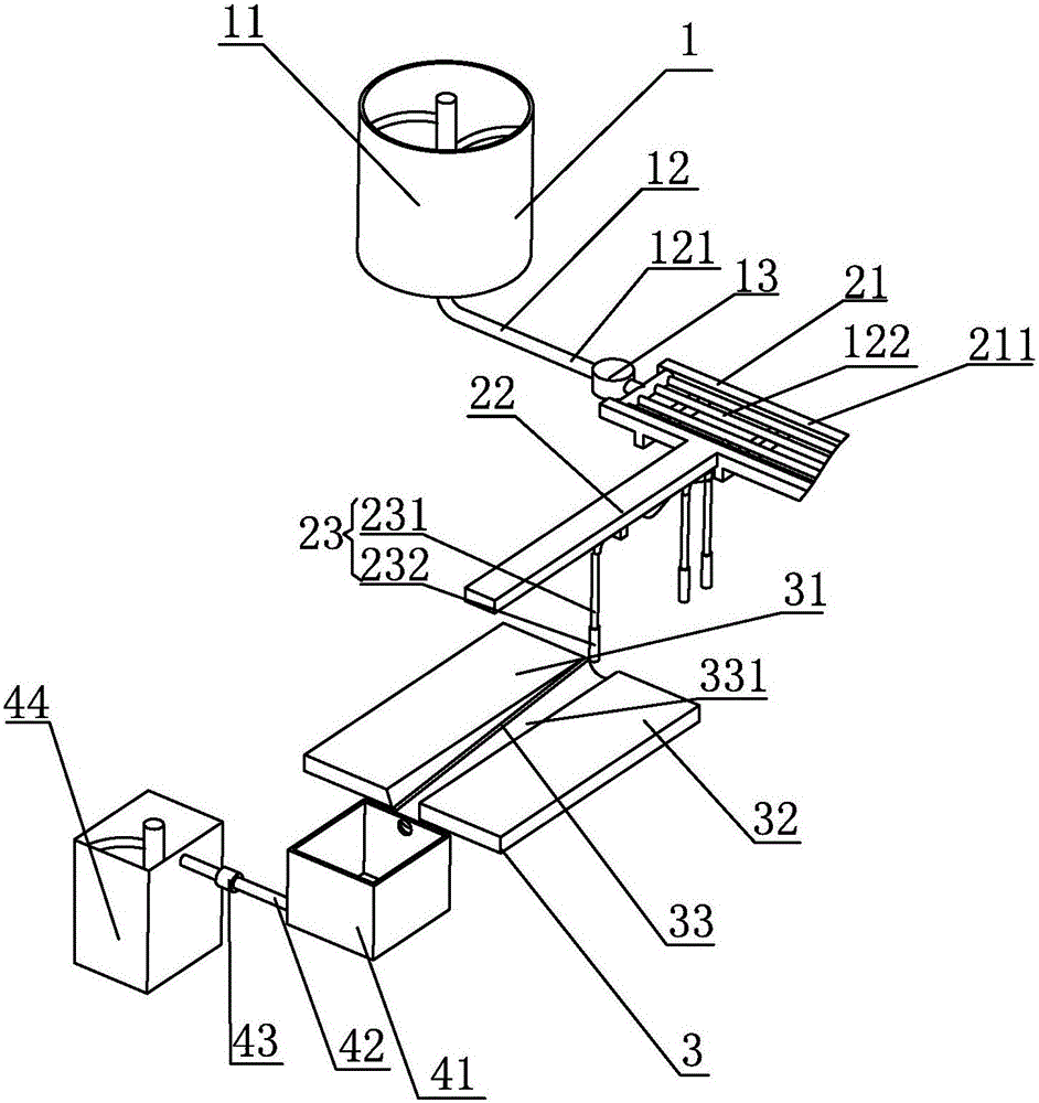
[0038] Specific embodiment two: as figure 2 As shown, the operating platform is single, and other components and structures are the same as those in Embodiment 1.

specific Embodiment 3

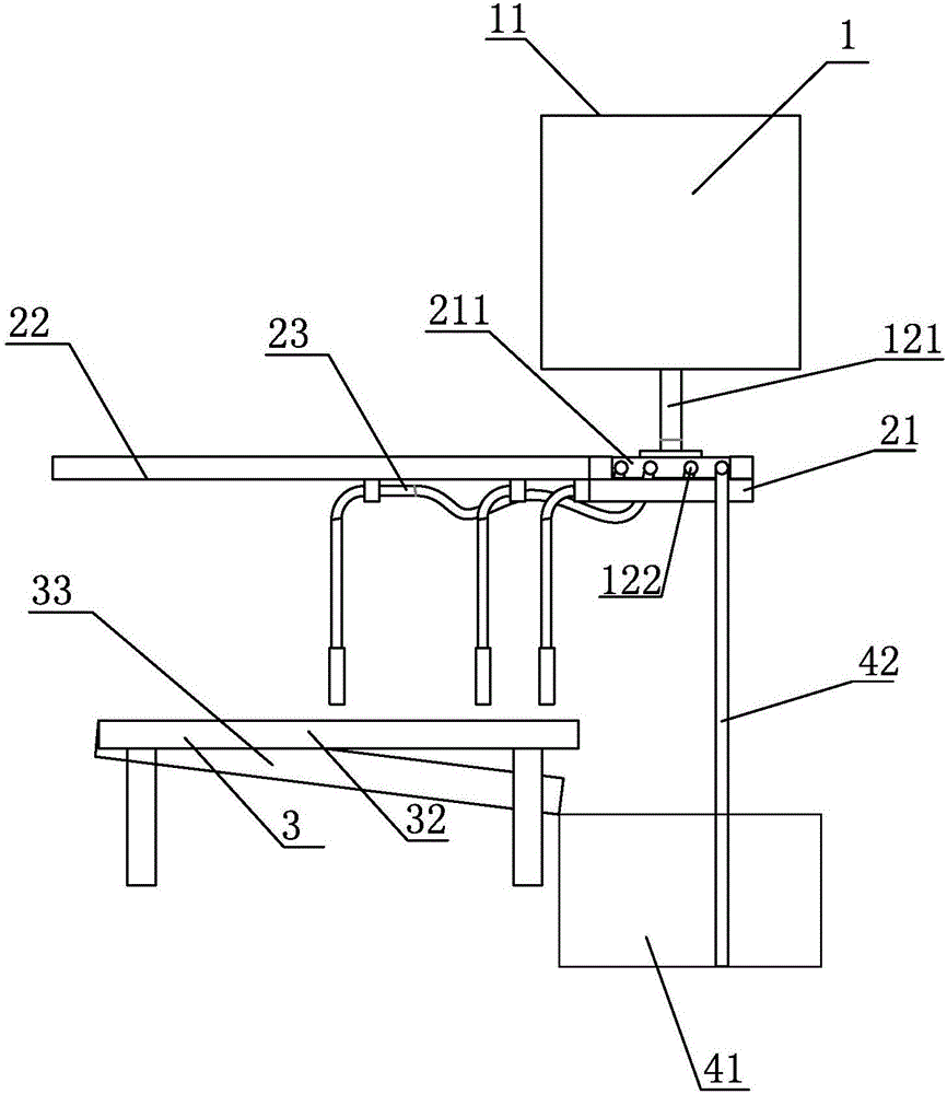
[0039] Specific embodiment three: as image 3 As shown, the waste collection bucket 41 is located directly below the frame 21, and other components and structures are the same as those in the first embodiment.


PUM


Abstract

The invention relates to the technical field of ceramic manufacturing equipment, in particular to ceramic grouting equipment with an automatic feeding function. The ceramic grouting equipment with the automatic feeding function comprises a feeding system, a grouting system, operating platforms and a waste recovery system. The feeding system comprises a grout mixing tank, a feeding pipeline and a booster pump. The grouting system comprises a rack, slide rails and a grouting device. The waste recovery system comprises a waste collecting barrel, a grout pumping and feeding pipeline, a grout pump and a waste mixing tank. By adoption of the ceramic grouting equipment with the automatic feeding function, the situation that the grout is not prone to sediment, the flow quantity and flow speed can be adjusted, different grout on different stations in the same workshop can operate, the billet quality can be improved, and the grout can be automatically recycled; and no manual cleaning is needed, the operating intensity is relieved, and the waste utilization rate is increased.

Description

technical field [0001] The invention relates to the technical field of ceramic manufacturing equipment, in particular to an automatic feeding ceramic grouting equipment and a grouting method. Background technique [0002] my country has a long history of ceramic production and application, and ceramic culture has a long history. With the continuous improvement of social science and technology and production level, ceramic production technology and equipment are constantly updated, transitioning from manual work to mechanization and automation. Therefore, the innovation of ceramic production process and the technical transformation of equipment are the urgent needs of today's society. Take the grouting in the production of ceramic wine bottle body as an example: [0003] The traditional grouting method is to pour the mud from the tank into the large grouting pot, and the workers hold the pot to fill each model. After the slurry suction process is over, control the excess s...

Claims


Application Information

Patent Timeline
IPC IPC(8): B28B13/02B28B1/26B28B17/00B28B15/00
CPCB28B13/021B28B1/26B28B15/00B28B17/00
Inventor 李国阳
Owner SHISHI TAIRUI PRECISION MACHINERY
Why Eureka
Try Eureka