Green brick overturning machine achieving accurate overturning of green bricks
A kind of adobe and adobe turning technology, which is applied in the direction of ceramic molding machines, auxiliary molding equipment, manufacturing tools, etc., and can solve problems such as adobe damage
- Summary
- Abstract
- Description
- Claims
- Application Information
AI Technical Summary
Problems solved by technology
Method used
Image
Examples
Embodiment 1
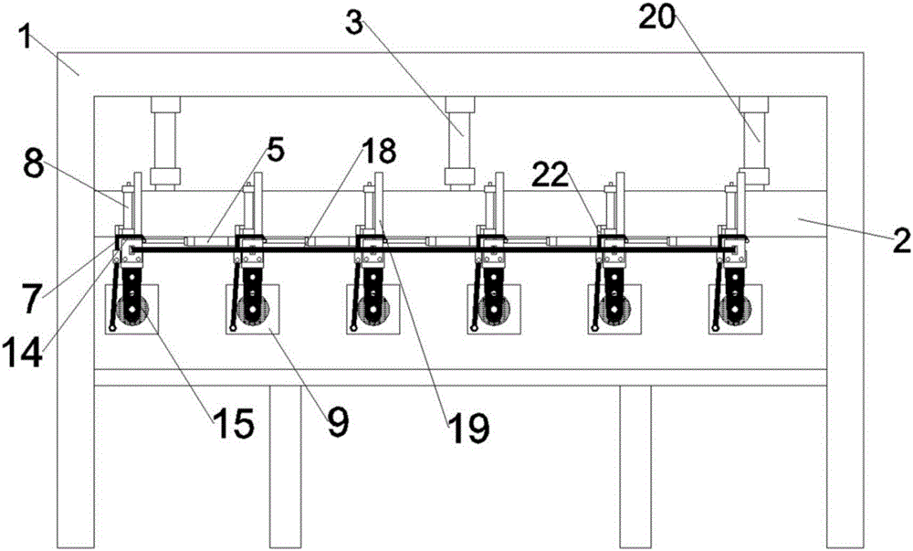
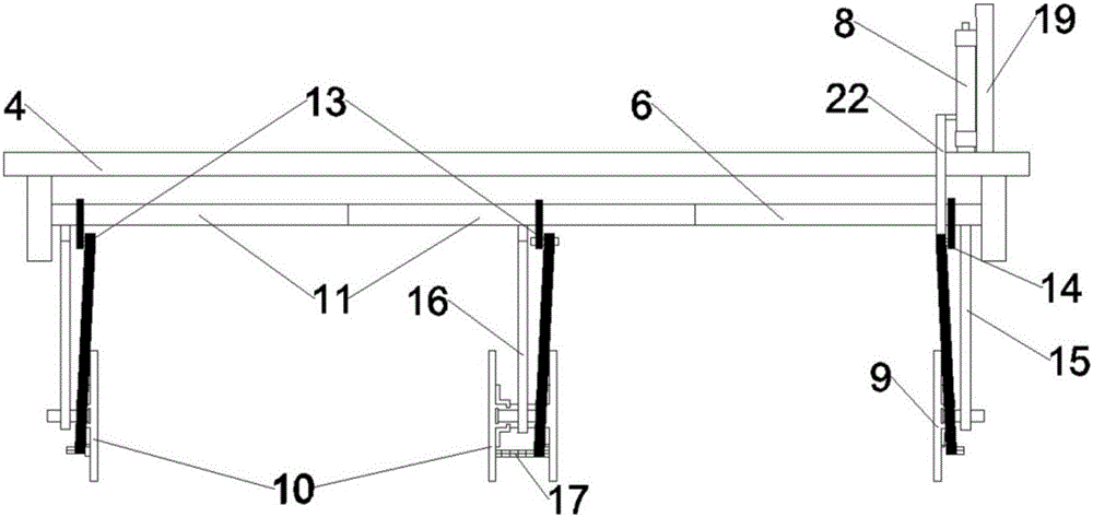
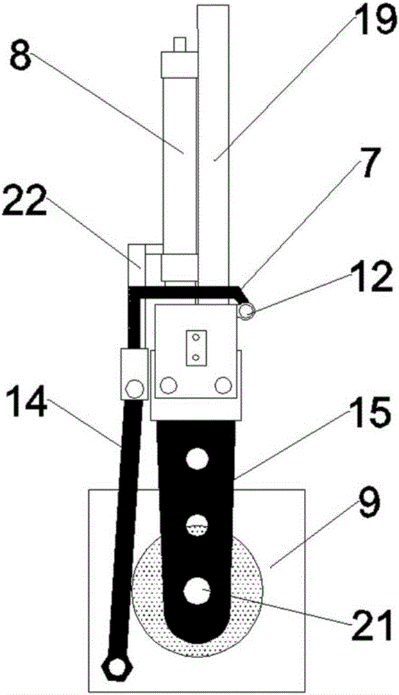
[0044] A turning machine for accurately turning brick adobes, comprising a basic frame 1, a main frame 2, a main cylinder 3 arranged between the basic frame 1 and the main frame 2, and a plurality of cylinders arranged below the main frame 2 that can slide along the main frame 2 The telescopic cylinder 5 of the movable crossbeam 4 arranged between the crossbeam 4 and a plurality of crossbeams 4; a linear guide rail 6 is arranged under each crossbeam 4, and a main splint 9 and a plurality of secondary splints 10 are arranged on the linear guide rail 6 A clamping cylinder 11 is provided between the auxiliary splint 10 and the linear guide rail 6; a transmission device 7 is also included, and the transmission device 7 includes a rotating shaft 12 arranged on the crossbeam 4, and the corresponding auxiliary splint 10 or the main splint 9 is fixed in position on the rotating shaft 12 A crank a13 or a crank b14 is provided, and the crank a13 or the crank b14 is respectively movably c...
Embodiment 2
[0046] This embodiment is further optimized based on Embodiment 1. The overturning cylinder 8 is vertically arranged above the main splint 9, and the ejector rod of the overturning cylinder 8 is fixedly connected with a transmission rod 22, which is movably connected with the crank b14, and no other components are needed in the middle. The structure is connected, the structure is simple, and the turning cylinder 8 is directly arranged on the top of the main splint 9, which is more convenient and accurate for adjusting the turning angle.
Embodiment 3
[0048] This embodiment is further optimized based on Embodiment 1, the main splint 9 is connected to the linear guide rail 6 through the main support plate 15, one end of the main support plate 15 is fixedly connected to the linear guide rail 6, and one end is movably connected to the main splint 9; Said auxiliary splint 10 is connected with the linear guide rail 6 through the auxiliary supporting plate 16 , one end of the auxiliary supporting plate 16 is fixedly connected with the ejector rod of the clamping cylinder 11 , and one end is movably connected with the auxiliary splint 10 .
PUM
 Abstract
Description
Claims
Application Information
 - R&D
- Intellectual Property
- Life Sciences
- Materials
- Tech Scout
- Unparalleled Data Quality
- Higher Quality Content
- 60% Fewer Hallucinations
Browse by: Latest US Patents, China's latest patents, Technical Efficacy Thesaurus, Application Domain, Technology Topic, Popular Technical Reports.
© 2025 PatSnap. All rights reserved.Legal|Privacy policy|Modern Slavery Act Transparency Statement|Sitemap|About US| Contact US: help@patsnap.com


