Efficient sound energy reducing type fluid purifying device

A technology of fluid purification and sound energy, applied in the direction of mufflers, exhaust devices, engine components, etc., can solve the problems that affect the life of the muffler that affects the muffler effect of the car, and the muffler is easy to block, so as to reduce the generation of intermediate products and improve the purification Efficiency, pollution reduction effect

Inactive Publication Date: 2017-03-15
CHENGDU LINGCHUAN SPECIAL IND
View PDF1 Cites 0 Cited by
  • Summary
  • Abstract
  • Description
  • Claims
  • Application Information

AI Technical Summary

Problems solved by technology

[0004] The purpose of the present invention is to provide a fluid purification device for effectively reducing sound energy, which solves the problem that the muffler in the prior art is easy to block, which affects the noise reduction effect of the car and the service life of the muffler; realizes preventing the muffler from being blocked and improving dust removal. Purification effect, the purpose of prolonging the service life of the muffler

Method used


Image

  • Efficient sound energy reducing type fluid purifying device

Examples


Embodiment 1

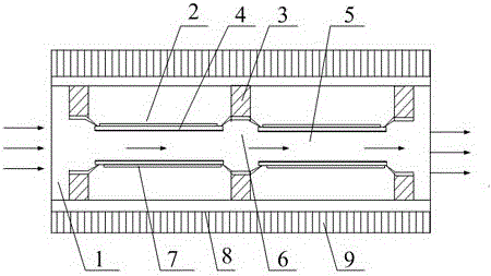
[0021] Such as figure 1 A fluid purification device for efficiently reducing sound energy shown includes a silencer 1, the silencer 1 is in the shape of a cuboid, and 2 purification groups 2 and 3 baffles 3 are arranged in the silencer 1, and N and M are equal to each other. is a positive integer, the purification groups 2 and baffles 3 are alternately arranged and fixed along the exhaust gas flow direction; each purification group 2 includes two insulating ceramic plates 4, and the two insulating ceramic plates 4 are arranged in parallel to each other. A purification channel 5 is formed between the insulating ceramic plates 4, and each baffle plate 3 is provided with a through hole 6, and the through hole 6 communicates with the purification channel 5, and an electrode plate 7 is respectively fixed on both sides of the purification channel 5 , the inner wall of the purification channel 5 is coated with nano-scale TiO2 photocatalyst; the two electrode plates 7 are respectively...

Embodiment 2

[0023] Such as figure 1 Shown is a fluid purification device for effectively reducing sound energy. On the basis of Embodiment 1, the working process of the present invention: after the car is started, the power supply connected to the electrode plate is connected, and the harmful particles in the exhaust gas enter the muffler along with the airflow Harmful particles enter the purification channel 5 in the first purification group through the through hole of the first baffle, and the discharge area in the purification channel 5 generates plasma, which absorbs the particles and plays a role in purification; at the same time, the inner wall of the purification channel 5 Under the catalysis of the ultraviolet lamp generated during discharge, the nano-scale TiO2 photocatalyst generates electron-hole pairs, and then performs redox degradation on the harmful gas molecules in the air adsorbed on the catalyst; then the unpurified gas molecules in the gas flow Harmful particles enter t...


PUM


Abstract

The invention discloses an efficient sound energy reducing type fluid purifying device. The device comprises a cuboid-shaped silencing tube, wherein N purifying sets and M baffle plates are arranged in the silencing tube, and N and M are positive integer; the purifying sets and the baffle plates are alternatively arranged and fixed along the exhaust gas flowing direction; each purifying set comprises two insulated ceramic plates which are arranged in parallel, and a purifying channel is formed between the two insulated ceramic plates; a through hole which communicates with each purifying channel is formed in each baffle plate; an electrode board is fixed to each of two sides of each purifying channel; a nano TiO2 photocatalyst is coated on the inner wall of each purifying channel. With the adoption of the device, the problem that a silencer in the prior art is easily blocked and thus the silencing effect and the service life of the silencer are influenced can be solved, and the purposes of preventing the silencer from being blocked, improving the dust removing and purifying effect and prolonging the service life of the silencer can be achieved.

Description

technical field [0001] The invention relates to a noise reduction device, in particular to a fluid purification device for effectively reducing sound energy. Background technique [0002] In modern civilization, cars have become an indispensable means of transportation for human beings. However, with the rapid development of the automobile industry and the continuous increase in automobile production and ownership, automobiles also bring air pollution, that is, automobile exhaust pollution. In large and medium-sized cities in China, vehicle exhaust emissions have become the main source of air pollution. According to data, the total number of cars in Shanghai is only 1 / 12 of that in Tokyo, Japan, but the total amount of CO, HC and NOx mainly emitted by cars in the air is basically the same. With the rapid development of the economy and the increase of social needs, the number of automobiles in use in China will increase substantially. This shows the urgency of reducing aut...

Claims


Application Information

Patent Timeline
Patent Type & Authority Applications(China)
IPC IPC(8): F01N3/28F01N1/10F01N3/01
CPCF01N3/2882F01N1/10F01N3/01F01N3/2885
Inventor 黄建军于隽
Owner CHENGDU LINGCHUAN SPECIAL IND
Why Eureka
Try Eureka