Novel vacuum compression system

A new type of vacuum compression technology, which is applied to parts of pumping devices for elastic fluids, non-variable pumps, pump devices, etc. It can solve the problem of reduced flow rate, inability to meet the requirements of large volume, and inability to increase without limit Problems such as pump volume specifications, etc., to achieve the effect of increasing the pumping capacity

Active Publication Date: 2017-03-15
淄博真空设备厂有限公司
View PDF6 Cites 3 Cited by
  • Summary
  • Abstract
  • Description
  • Claims
  • Application Information

AI Technical Summary

Problems solved by technology

[0003] 1. The liquid ring pump is limited by the linear speed of impeller rotation, so it cannot increase the volume specification of the pump without limit. Efficiency is reduced, and at the same time, the overall size and unit weight of the equipment will increase geometrically, resulting in difficulties in manufacturing, transportation, installation and maintenance
[0004] 2. At present, most high-discharge compressors use single-shaft, double-impeller, and two-stage compression. The structure is complex, the processing and manufacturing precision is high, and the pumping volume is small, which cannot meet the air volume requirements.
For a compressor with a large pumping capacity, the only way to increase the specification can be used, but the flow rate drops sharply when the exhaust pressure is high, and it cannot adapt to the variable flow rate and variable pressure conditions

Method used


Image

  • Novel vacuum compression system
  • Novel vacuum compression system
  • Novel vacuum compression system

Examples


Embodiment Construction

[0020] The present invention will be further described below in conjunction with accompanying drawing:

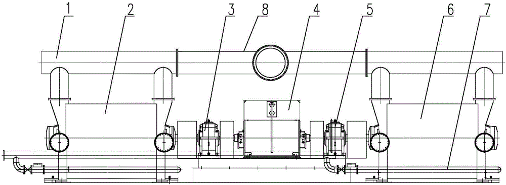
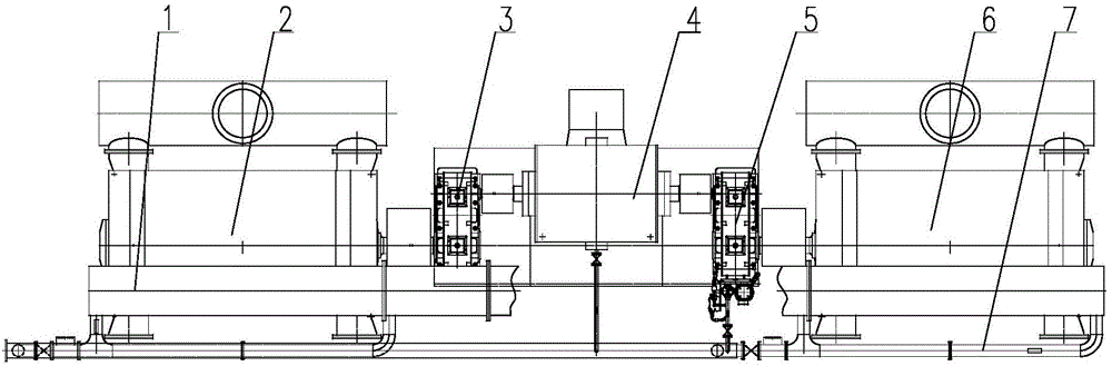
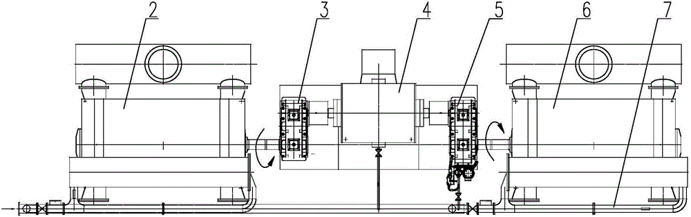
[0021] Such as Figure 1 to Figure 5 As shown, the novel vacuum compression system of the present invention includes a motor 4, the motor 4 is a double-shaft motor 4, and the two output ends are respectively connected to the vacuum pump A2 through the reducer A3, connected to the vacuum pump B6 through the reducer B5, the vacuum pump A2 and the vacuum pump B6 are double-suction vacuum pumps, the air inlets of vacuum pump A2 and vacuum pump B6 are respectively connected to the air inlet pipe 1, and the two air inlet pipes 1 are connected to the general air inlet of the vacuum system through the air inlet tee 8, and the exhaust ports of vacuum pump A2 and vacuum pump B6 connected to the exhaust pipe respectively. Both the vacuum pump A2 and the vacuum pump B6 are connected to the sealed cooling system 7, and the sealed cooling system 7 includes a cooling main pipe, and the v...


PUM


Abstract

The invention is mainly applied to the field of vacuum equipment and particularly relates to a novel vacuum compression system. The novel vacuum compression system comprises a motor. The motor is a double-shaft extension motor. One output end of the motor is connected with a vacuum pump A through a speed reducer A, and the other output end of the motor is connected with a vacuum pump B through a speed reducer B. The vacuum pump A and the vacuum pump B are both double-suction vacuum pumps. Air inlets of the vacuum pump A and the vacuum pump B communicate with air inlet pipes correspondingly. The two air inlet pipes communicate with a main air inlet of a vacuum system through an air inlet T-joint. Through the novel vacuum compression system, a vacuum unit can be made to operate at an optimum performance working point in a matched mode, and the technical requirements for the large air pumping amount are met. A driver and the pumps can be controlled through clutches. The air pumping amount can be increased when the two pumps operate in parallel. The compression ratio can be increased, and the air discharge pressure can be increased.

Description

technical field [0001] The invention relates to a novel vacuum compression system, which is mainly used in the field of vacuum equipment. Background technique [0002] With the continuous development of aerospace, petroleum, chemical industry, coal mine, papermaking and other industries, the requirements for the performance, efficiency, operation reliability and transportation safety of vacuum equipment are constantly improving, especially for large pumping capacity, high vacuum, high Existing single liquid ring vacuum pumps or compressors cannot meet the technological conditions of exhaust pressure. This is because: [0003] 1. The liquid ring pump is limited by the linear speed of impeller rotation, so it cannot increase the volume specification of the pump without limit. Efficiency is reduced, and at the same time, the overall size and unit weight of the equipment will increase geometrically, resulting in difficulties in manufacturing, transportation, installation and m...

Claims


Application Information

Patent Timeline
Patent Type & Authority Applications(China)
IPC IPC(8): F04D17/10F04D25/16F04D25/06F04D29/58
Inventor 徐法俭赵彩霞黄志婷蒋虎宋道村袁铮
Owner 淄博真空设备厂有限公司
Why Eureka
Try Eureka