Air ventilation model for hydraulic test

A technology of model and introduction tube, which is applied in fluid dynamics test, machine/structural component test, measuring device, etc., can solve problems such as unsatisfactory test requirements, expand the space for internal pressure stabilization, and satisfy large ventilation volume The effect of demand, length shortening

Active Publication Date: 2017-03-15
CHINA ACAD OF LAUNCH VEHICLE TECH
View PDF4 Cites 6 Cited by
  • Summary
  • Abstract
  • Description
  • Claims
  • Application Information

AI Technical Summary

Problems solved by technology

Due to the limited space inside the model, only small-diameter ventilation lines can be used, so it cannot meet the needs of experiments that require large-flow ventilation or multiple ventilation

Method used


Image

  • Air ventilation model for hydraulic test
  • Air ventilation model for hydraulic test

Examples


Embodiment Construction

[0026] Below in conjunction with accompanying drawing and specific embodiment the present invention is described in further detail:

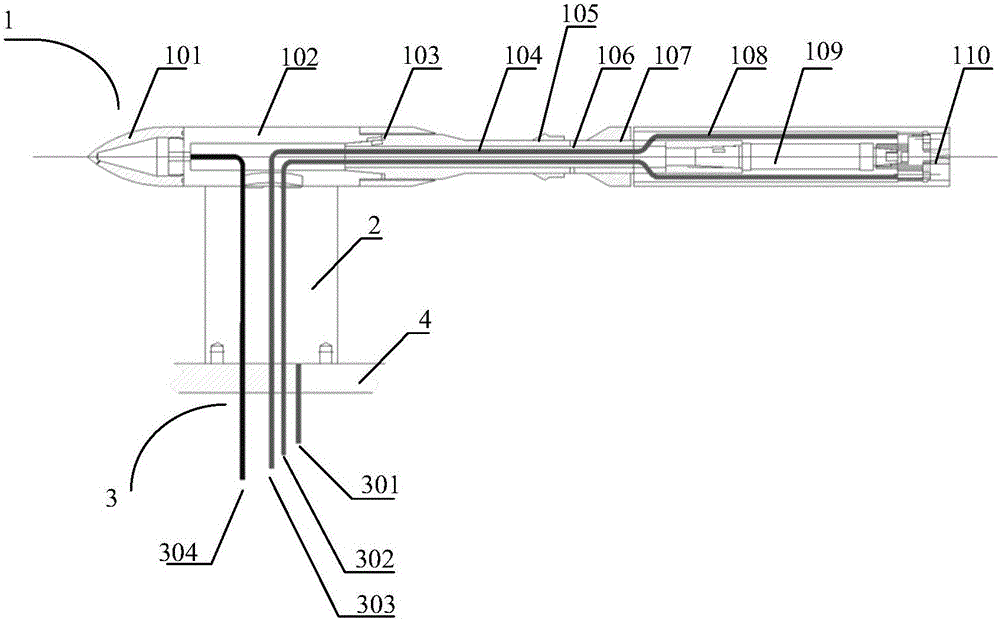
[0027] The underwater test ventilation model of the present invention is a similar scale model after the vehicle body is scaled down, and is used for the water tunnel test of the vehicle body, and mainly includes a main body 1 , a supporting airfoil 2 and a pipeline 3 .

[0028] (1) Main part

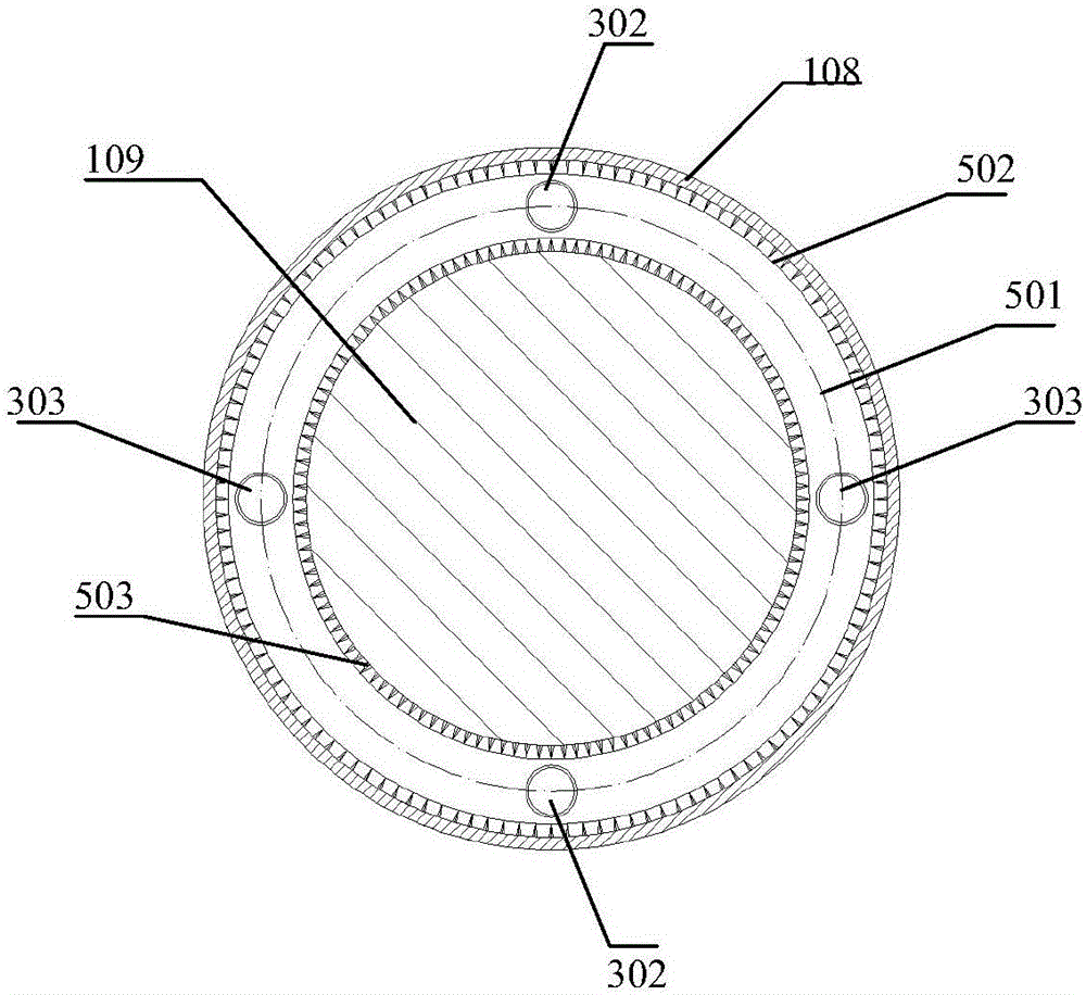
[0029] Such as figure 1 As shown in the vertical axis sectional view, the main part 1 of the water test ventilation model provided by the present invention consists of a head 101, a front section 102, a connecting sleeve 103, a tail support sleeve 104, a cavitator 105, a vent hole 106, and a cone after deflation. Pipe 107, rear section outer casing 108, six-component balance 109, nozzle 110 constitute.

[0030] Wherein, the head 101 is connected to the front section 102, and the other end of the front section 102 is connected to the supporting tail sect...


PUM


Abstract

The invention discloses an air ventilation model for hydraulic test. The model is a similar model for a navigation body undergoing scale ratio reduction and is used for the hydraulic test for the navigation body. The model of the invention comprises a main body part, support wing models and channels wherein the support wing models adopt a hollow structure and can serve as air pressure stabilizing space together with the empty cavity inside the main body. In this design, the lengths of the channels inside the model are shortened, making the channels occupy less space and enlarging the pressure stabilizing space inside. Or rather, the utilization efficiency of internal space of the model is increased while the requirement for large air ventilation is satisfied. In addition, the air ventilation channels of the invention are divided into discharged air inlet channels at the middle and the tail, which realize the air ventilation from the front and the back and effectively solves the excessive concentration of the multiple ventilation channels in small scale hydraulic tests.

Description

technical field [0001] The invention relates to the technical field of small-scale model design, in particular to an underwater test ventilation model. Background technique [0002] Due to the complexity and strong coupling of the working environment, the nonlinearity of the equation of motion, and the complexity of the boundary conditions for key components such as various types of vehicles in the water, it is difficult to obtain analytical solutions to hydrodynamics and kinematics problems using mathematical methods , and it is difficult to obtain accurate parameters using simulation methods, and various water tests must be conducted to study the formation mechanism of important phenomena and obtain characteristic parameters. However, in engineering practice, if the prototype of the aircraft and the key layout is directly used for the test, it is often difficult to proceed smoothly due to the large geometric size, difficulty in processing, material cost, test period, and t...

Claims


Application Information

Patent Timeline
Patent Type & Authority Applications(China)
IPC IPC(8): G01M10/00
CPCG01M10/00
Inventor 赵静陆宏志惠俊鹏康磊晶李一帆魏洪亮刘丽丽耿斌斌
Owner CHINA ACAD OF LAUNCH VEHICLE TECH
Why Eureka
Try Eureka