Electric equipment and its motion control method

An electric and equipment technology, applied in the direction of electric speed/acceleration control, etc., can solve the problems of inability to respond to the position information of the transmission module in real time, the influence of system stability and service life, and the addition of position sensors or grating encoders.

Active Publication Date: 2021-06-15
NANJING MINDRAY BIO MEDICAL ELECTRONICS
View PDF0 Cites 0 Cited by
  • Summary
  • Abstract
  • Description
  • Claims
  • Application Information

AI Technical Summary

Problems solved by technology

[0003] Since the limit switch can only detect the state of the upper and lower limit positions or the left and right limit positions, it cannot reflect the position information of the transmission module in real time
If you want to obtain real-time position information of the transmission module, the existing method is to add complex hardware modules such as position sensors or grating encoders
In addition, once the limit switch is triggered, the transmission module needs to respond in a timely manner, without buffer time, it is easy to cause destructive hazards such as vibration and current overshoot, which has a great impact on the stability and service life of the system

Method used


Image

  • Electric equipment and its motion control method
  • Electric equipment and its motion control method

Examples


Embodiment 1

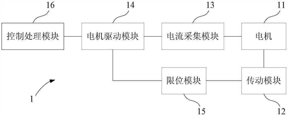
[0012] like figure 1 As shown, the electric device 1 provided in this embodiment includes: a motor 11 , a transmission module 12 , a current collection module 13 , a motor drive module 14 , a limit module 15 and a control processing module 16 . Each module is described in detail below, and the corresponding motion control method of the electric device is explained through the description.

[0013] The motor 11 is a power conversion device of the electric device 1 , and the parameters of different motors are different, so in practical applications, the parameters of the motor are determined by the specific motor model. In this embodiment, the motor 11 may be a DC motor.

[0014] The transmission module 12 is a mechanical transmission mechanism controlled by the motor 11, which realizes the conversion from the rotation of the motor to the linear motion. Taking the electric device as a medical pendant as an example, the transmission module 12 is the mechanical application trans...

Embodiment 2

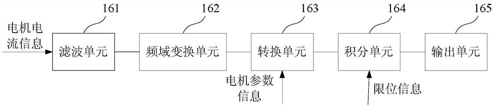
[0024] This embodiment is an improvement made on the basis of Embodiment 1, specifically: considering that there is an accumulated error in the integration, after a period of use, the position deviation will become larger and larger, so the control processing module 16 of this embodiment also It is used to adjust the integral constant in the integral unit 164 to the value corresponding to the limit position when the limit module 15 is triggered. In this way, the limit module 15 will be used as the position reference of the transmission module 12. When the limit module 15 is triggered, the integral unit 164 of the control processing module 16 will correct the constant of the integral part, thereby clearing the cumulative error of the integral and ensuring the long-term operation of the system. accuracy. It can be seen that the online real-time calibration of the electric device 1 can be realized in combination with the limit module 15 , without additional calibration and calibr...


PUM


Abstract

This application relates to electric equipment and its motion control method. The equipment includes: a control processing module; a motor; a transmission module controlled by the motor; The control processing module; the limit module is used to limit the limit position of the transmission module and feed back the limit position to the control processing module; the control processing module is used to analyze the speed information of the motor according to the current signal and the motor parameters of the motor. Limit position and speed information determine the current position of the transmission module, and control the driving parameters of the motor according to the current position. By analyzing the motor current information, the motor speed information is extracted from it, and then the current position of the transmission module is calculated according to the limit position. In the whole process, the position detection can be realized without adding additional hardware, and the speed control of the transmission module can be realized. It is possible to work stably and safely.

Description

technical field [0001] The present application relates to the technical field of electric equipment, in particular to an electric equipment and a motion control method thereof. Background technique [0002] The use of electric equipment is one of the essential means for hospitals to achieve modernization, such as medical pendants, operating beds, etc. For various motion and position control equipment, limit switches are usually used to control the limit of its moving parts, that is, limit switch components are fixedly installed at the places where the moving parts pass through and need to be limited. The range of movement of the moving parts can be limited to the range required by the work through the limit switch. Once the limit switch fails, it may cause damage to the equipment or accidents. Therefore, the stability and reliability of the limit switch is very important for various sports and It is very important for position control equipment. [0003] Since the limit sw...

Claims


Application Information

Patent Timeline
Patent Type & Authority Patents(China)
IPC IPC(8): G05D13/62
Inventor 张丽宏吴明春
Owner NANJING MINDRAY BIO MEDICAL ELECTRONICS
Why Eureka
Try Eureka