Built-in common-mode electric reactor of three-phase electric reactor

A technology of three-phase reactors and reactors, which is applied in the direction of inductors, fixed inductors, transformer/inductor cores, etc., can solve the problem of inability to filter out zero-sequence common-mode harmonics, difficulty in satisfying inductance, and large common-mode Harmonic and other problems, to achieve the effect of reducing body size, improving performance and saving materials

Active Publication Date: 2017-03-15
上海意兰可电力电子设备有限公司
View PDF7 Cites 2 Cited by
  • Summary
  • Abstract
  • Description
  • Claims
  • Application Information

AI Technical Summary

Problems solved by technology

When the three-phase circuit contains high zero-sequence common-mode components, the vector sum of the magnetic fluxes in the three iron core columns wound with coils is not zero, and the zero-sequence common-mode harmonics cannot be filtered out by using conventional three-phase reactors. Wave
If three-phase four-column reactors, three-phase five-column reactors, or three single-phase reactors are used instead, although zero-sequence common-mode inductance can be generated, its common-mode inductance is equivalent to that of three-phase differential-mode inductance, and it is difficult to meet the requirements of the above circuit. The inductance required to filter the common mode harmonic content in the circuit
[0004] With the development of power electronics technology, when the capacity of the converter is large, it is often necessary to use two inverter modules in parallel to output, but it often contains large common-mode harmonics

Method used


Image

  • Built-in common-mode electric reactor of three-phase electric reactor
  • Built-in common-mode electric reactor of three-phase electric reactor
  • Built-in common-mode electric reactor of three-phase electric reactor

Examples


Embodiment Construction

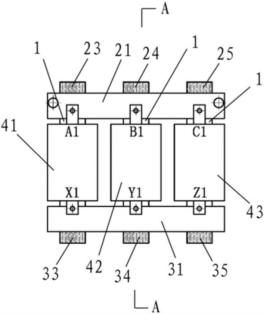
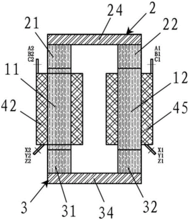
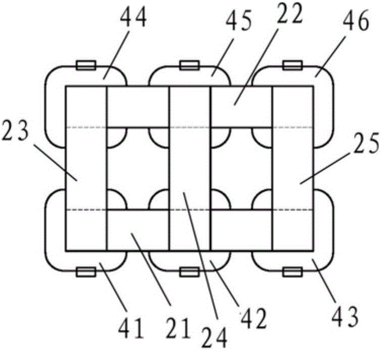
[0035] Such as Figure 1-4 The three-phase reactor shown has a built-in common mode reactor, including six iron core columns 1 , five upper iron yokes 2 and five lower iron yokes 3 .

[0036] For the convenience of description, the six iron core columns are respectively referred to as the first iron core column, the second iron core column, the third iron core column, the fourth iron core column, the fifth iron core column, and the sixth iron core column; The upper iron yokes are respectively called the first upper iron yoke 21, the second upper iron yoke 22, the third upper iron yoke 23, the fourth upper iron yoke 24, and the fifth upper iron yoke 25; the five lower iron yokes are respectively called The first lower iron yoke 31 , the second lower iron yoke 32 , the third lower iron yoke 33 , the fourth lower iron yoke 34 , and the fifth lower iron yoke 35 .

[0037] Each iron core column 1 is wound with a coil 4 , corresponding to each iron core column, respectively coil 41...


PUM


Abstract

The invention relates to a built-in common-mode electric reactor of a three-phase electric reactor, and aims to provide the built-in common-mode electric reactor of the three-phase electric reactor used for two groups of three-phase inversion output side filtering circuits in a parallel operation for filtering difference mode harmonics as well as common-mode harmonics. The built-in common-mode electric reactor of the three-phase electric reactor comprises six iron core columns, five upper iron yokes, and five lower iron yokes, wherein each iron core column is wound by a coil separately; an air gap is formed in each iron core column; the six iron core columns are divided into two groups by taking three iron core columns as one group; one iron core column group is arranged between one upper iron yoke and one lower iron yoke in parallel while the other iron core column group is arranged between another upper iron yoke and another lower iron yoke in parallel; the last three upper iron yokes are arranged above the above-mentioned two upper iron yokes in parallel while the last three lower iron yokes are arranged below the above-mentioned two lower iron yokes in parallel; and the dotted terminal of each phase of coils of one iron core column group and the dotted terminal of each phase of coils of the other iron core column group are connected together to form the common-mode electric reactor.

Description

technical field [0001] The present invention relates to a kind of electric power equipment, in particular to a three-phase reactor built-in common mode reactor. Background technique [0002] In the common three-phase inverter output circuit, the proportion of zero-sequence components is not large, and only a three-phase sine wave filter reactor needs to be connected to the output side of the inverter. When some special three-phase inverter circuits have large common-mode harmonic content, conventional three-phase reactors cannot generate large common-mode inductance and play a role in filtering common-mode harmonics. [0003] A conventional three-phase reactor consists of three iron core columns wound with coils and upper and lower iron yokes. When the three-phase circuit contains high zero-sequence common-mode components, the vector sum of the magnetic fluxes in the three iron core columns wound with coils is not zero, and the zero-sequence common-mode harmonics cannot be ...

Claims


Application Information

Patent Timeline
Patent Type & Authority Applications(China)
IPC IPC(8): H01F17/04H01F3/14H01F27/24
CPCH01F3/14H01F17/045H01F27/24
Inventor 徐启惠曹仲飞曹祥雄
Owner 上海意兰可电力电子设备有限公司
Why Eureka
Try Eureka