

Loudspeaker diaphragm tester with controlled excitation source
A technology of excitation source and loudspeaker, which is applied in the direction of electrical components, etc., can solve the problems of no effective monitoring of the driving loudspeaker, great influence on stability, and relatively high airtightness requirements between the diaphragm to be tested and the test tooling
- Summary
- Abstract
- Description
- Claims
- Application Information
AI Technical Summary
Problems solved by technology
Method used
Image

Examples
Embodiment 1
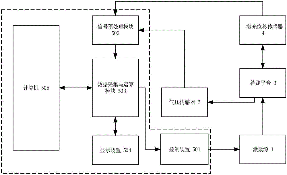
[0120] This embodiment provides a speaker diaphragm tester with a controlled excitation source. The controlled excitation source is a speaker excitation system with air pressure sensor feedback. The system connection diagram is as follows figure 1 shown. This embodiment includes: 1. excitation source; 2. air pressure sensor; 3. platform to be tested; 4. laser displacement sensor; 5. data processor; 501. control device; 502. signal preprocessing module; 503. data acquisition and Operation module; 504, display device; 505, computer. Among them, the control 501 , the signal preprocessing module 502 , the data acquisition and calculation module 503 , the display device 504 , and the computer 505 are collectively referred to as the data processor 5 .
[0121] The control device 501 is used to output the excitation signal to the excitation source 1; the signal processing module 502 is used to receive the detection signals of the air pressure sensor 2 and the laser displacement sens...
Embodiment 2
[0133] This embodiment provides a loudspeaker diaphragm tester with a controlled excitation source. The controlled excitation source is a cylinder with air pressure sensor feedback. The system connection diagram is as follows figure 1 shown. The system connection and data detection method of the data processor 5 in this embodiment are similar to those in the first embodiment, only the excitation source 1 is changed from the speaker 101 to the air cylinder 103 .
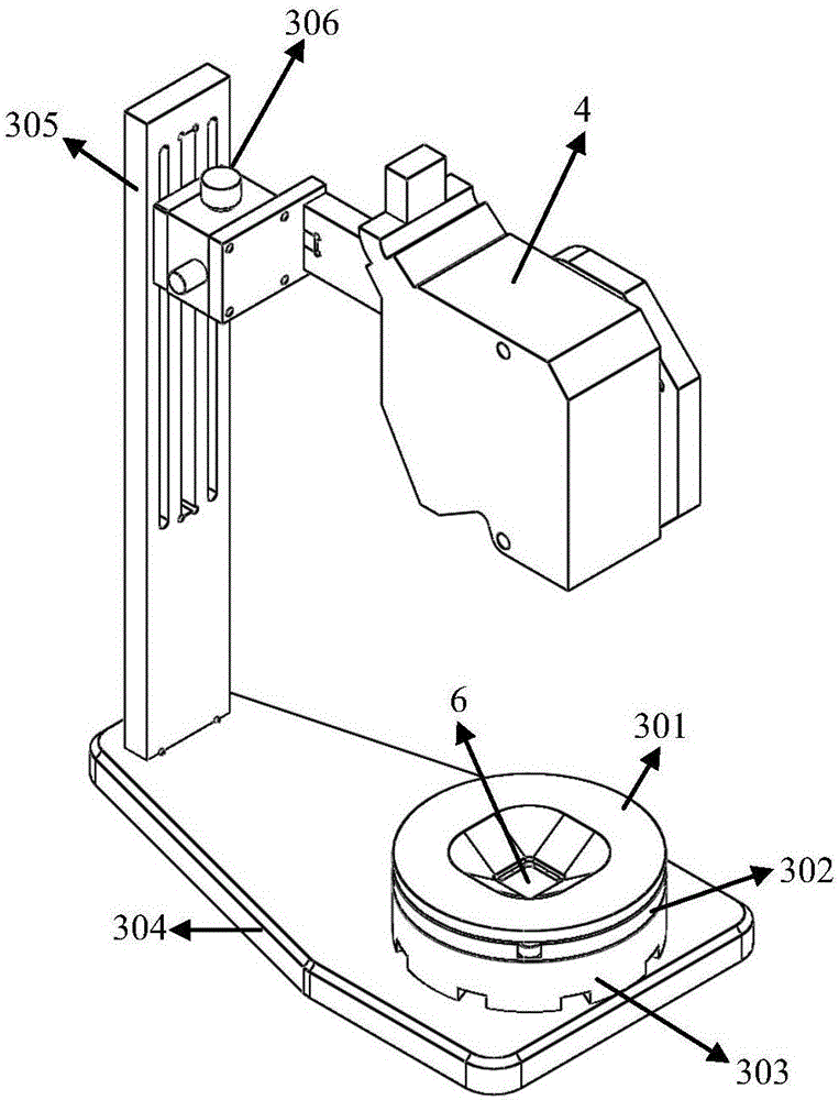
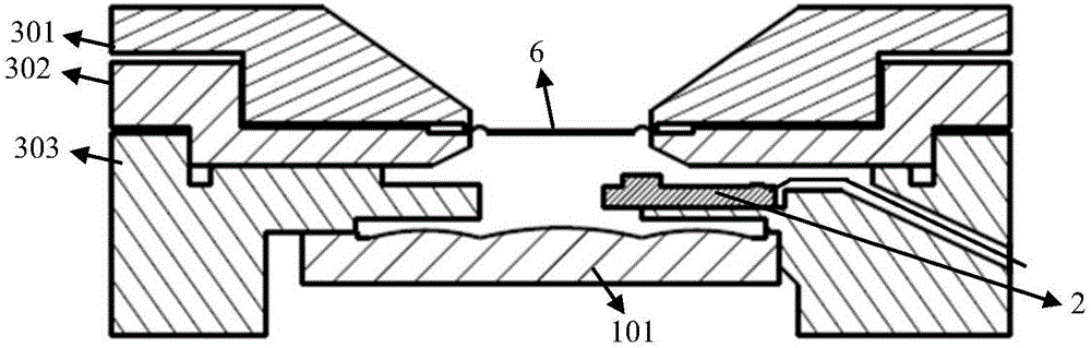
[0134] Figure 6 It is a schematic diagram of the appearance provided by this embodiment. The diaphragm 6 to be tested is fixed by an upper pressing tool 301 and a lower pressing tool 302 . The lower pressing tool 302 is combined with the abutment 303 to form a sealed cavity, and a leakage hole 9 is set in the sealed cavity. A channel is provided on the base platform 303, and is connected with the cylinder 103 through an air pipe. The abutment 303 is assembled on the base 304, and its horizontal position is adjust...
Embodiment 3
[0140] This embodiment provides a speaker diaphragm tester with a controlled excitation source. The controlled excitation source is a stepping rod motor excitation system with air pressure sensor feedback. The system connection diagram is as follows figure 1 shown. The system connection, data detection, and data processing methods of the data processor 5 in this embodiment are similar to those in the second embodiment, only the excitation source 1 is changed from the cylinder 103 to the stepper push rod motor 102 .
[0141] Figure 9 It is a schematic diagram of the appearance provided by this embodiment. The diaphragm 6 to be tested is fixed by an upper pressing tool 301 and a lower pressing tool 302 . The lower pressing tool 302 is combined with the abutment 303 to form a closed cavity. A channel is provided on the base platform 303, and is connected with the stepping rod motor 102 through an air pipe. The abutment 303 is assembled on the base 304, and its horizontal pos...
PUM
 Abstract
Description
Claims
Application Information