Laser Gyro Embedded Jitter Mechanism
A technology of shaking mechanism and laser gyroscope, applied in Sagnac effect gyroscope and other directions, can solve the problems of large cone motion, affecting the performance of laser gyroscope, etc., to improve verticality, ensure achievability, and reduce possibility
sexual effect
Inactive Publication Date: 2014-04-23
FLIGHT AUTOMATIC CONTROL RES INST
View PDF0 Cites 0 Cited by
- Summary
- Abstract
- Description
- Claims
- Application Information
AI Technical Summary
Problems solved by technology
When the central axis of the vibration cavity is not perpendicular to the shaking mechanism, a large cone motion will be generated, which will seriously affect the performance of the laser gyro
Method used
View moreImage
Smart ImageViewing Examples

Examples
Embodiment Construction
Login to View More PUM
 Abstract
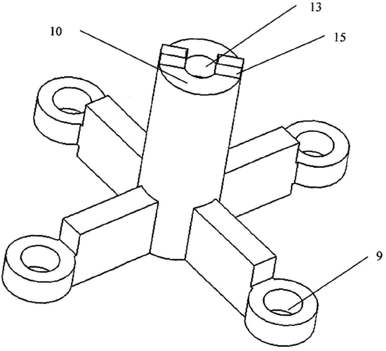
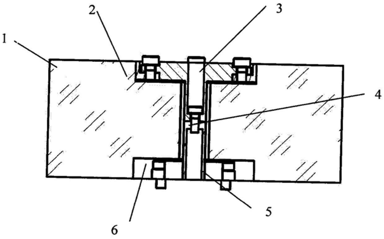
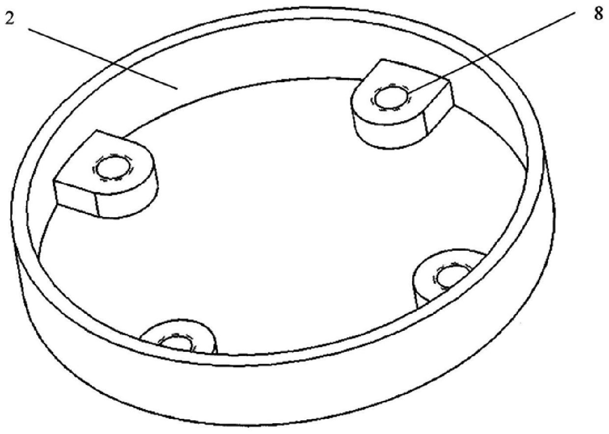
The invention relates to a laser gyro embedded shaking mechanism, which comprises a laser resonant cavity, a sleeve, an upper shaking mechanism, a lower shaking mechanism, piezoelectric ceramics and fastening screws. Wherein, the inner cylindrical surface of the blind hole on the laser resonator cavity and the outer cylindrical surface of the sleeve are pasted together, and the sleeve and the upper shaking mechanism are connected by screws. The connection between the bottom surface of the upper shaking mechanism and the top surface of the lower shaking mechanism is fastened by the central screw. The upper shaking mechanism processes the step through hole, the lower shaking mechanism processes the stepped threaded hole, the bottom surface of the upper shaking mechanism processes the key, and the lower shaking mechanism top The keyway is processed on the surface, and the relative movement of the two parts is limited after assembly, and the angle between the spokes of the two parts is 90°; the lower shaking mechanism is fixed on the shell by fastening screws through the through hole. Piezoelectric ceramics are pasted on both sides of the spokes of the up and down shaking mechanism. On the premise of ensuring the performance of the laser gyroscope, the invention makes the structure compact by embedding the shaking mechanism into the resonant cavity, and realizes the miniaturization of the laser gyroscope.
Description
Laser gyroscope embedded shaking mechanism technical field [0001] The present invention relates to a laser gyro embedded shaking mechanism. Background technique Laser gyroscope is a kind of optical gyroscope utilizing the Sagnac principle to develop, and in the laser gyroscope cavity, there is positive In contrast to the two running beams, the beat frequency signal generated by the interference of the two beams is proportional to the angular velocity of the gyroscope. When the input speed is absolute When the value is very small, the frequency of the beat frequency signal output by the gyro is 0, that is, the gyro produces a locking phenomenon. The jitter mechanism is excited by the alternating signal Under the excitation, an additional bias rate is generated on the laser gyro, so that the laser gyro mainly works outside the locked area, reducing the impact of the locked area on the laser effect on gyroscope performance. Traditionally, laser gyro shaking mechanism ...
Claims
Login to View More Application Information
Patent Timeline
 IPC IPC(8): G01C19/70G01C19/66
Inventor 张明辉郭昕韩宗虎
Owner FLIGHT AUTOMATIC CONTROL RES INST
Features
- R&D
- Intellectual Property
- Life Sciences
- Materials
- Tech Scout
- Unparalleled Data Quality
- Higher Quality Content
- 60% Fewer Hallucinations
Learn More Browse by: Latest US Patents, China's latest patents, Technical Efficacy Thesaurus, Application Domain, Technology Topic, Popular Technical Reports.
© 2025 PatSnap. All rights reserved.Legal|Privacy policy|Modern Slavery Act Transparency Statement|Sitemap|About US| Contact US: help@patsnap.com