Dust removing system for smelting waste gas

A technology for dust removal system and waste gas, which is applied to the separation of dispersed particles, chemical instruments and methods, and filtration of dispersed particles, etc., can solve the problems of short service life of filter bags, increase production costs, harm workers' bodies, etc. Production costs, environmental protection and worker health effects

Active Publication Date: 2017-03-22
HUNAN JIANXUN ENVIRONMENTAL PROTECTION RESOURCE SCI & TECH DEV
View PDF5 Cites 2 Cited by
  • Summary
  • Abstract
  • Description
  • Claims
  • Application Information

AI Technical Summary

Problems solved by technology

There are some disadvantages in the above method: First, when the worker pulls out the insert plate at the bottom of the funnel to collect dust, part of the exhaust gas overflows from the bottom of the funnel, causing the environment to be polluted and endangering the health of the workers.
Second, because the dust is dry, some of the dust will float into the air during the process of the dust falling, which also causes the environment to be polluted.
The third is that the temperature of the exhaust gas from the smelting furnace is very high, and the high-temperature exhaust gas damages the filter bag in the filter chamber q

Method used


Image

  • Dust removing system for smelting waste gas
  • Dust removing system for smelting waste gas
  • Dust removing system for smelting waste gas

Examples


Embodiment Construction

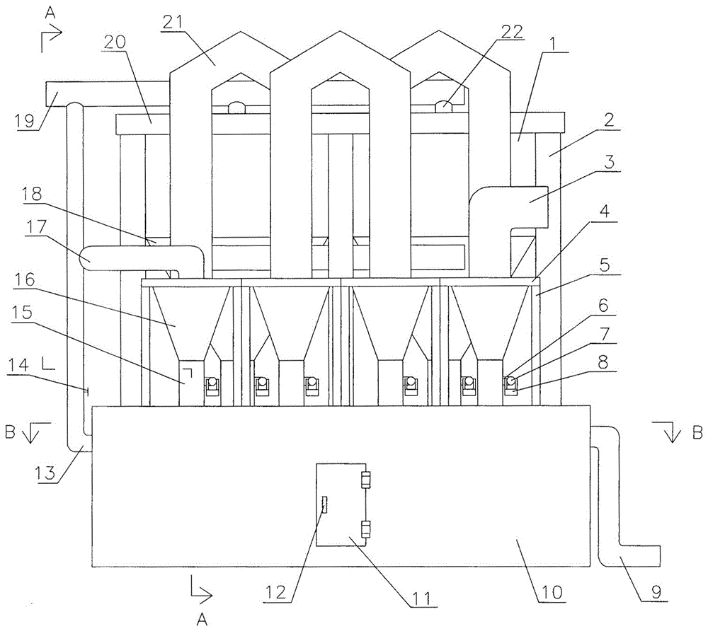
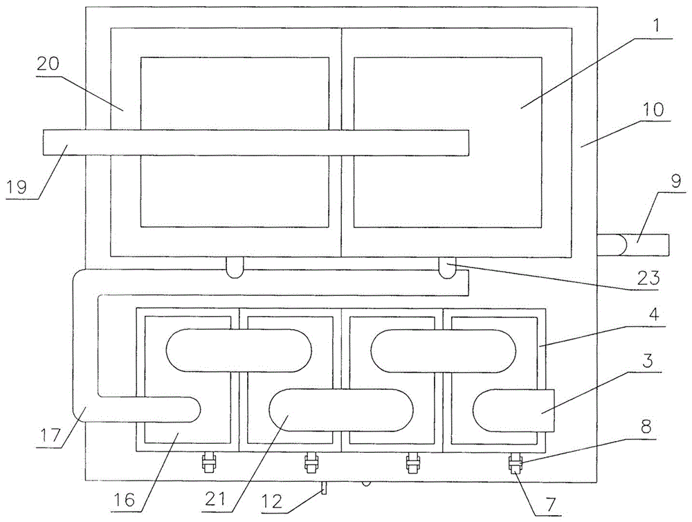
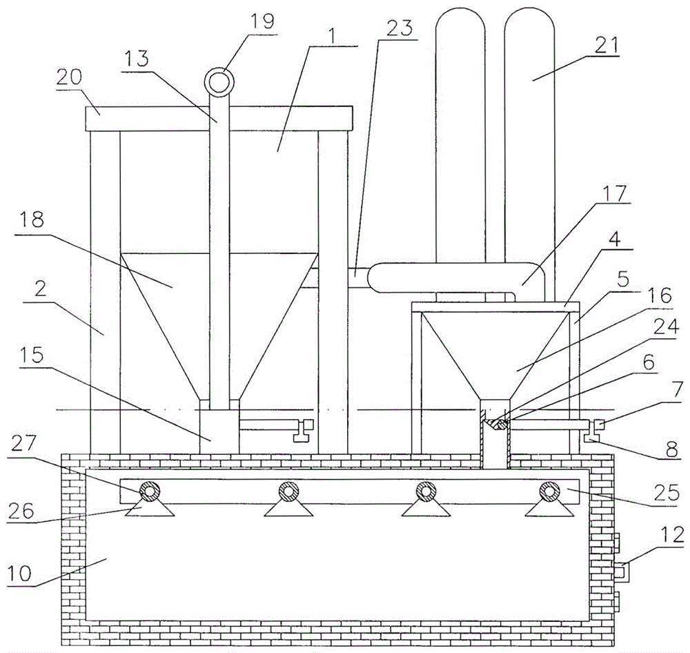
[0015] exist figure 1 , figure 2 , image 3 , Figure 4 In the shown embodiment, the dust collecting room 10 is built on the ground, and there is a door 11 on one wall of the dust collecting room 10; There is a valve 14 on the pipe 13; the water inlet pipe 9 communicates with the main water pipe 25 in the dust collection chamber 10, one end of a group of branch water pipes 27 communicates with the main water pipe 25, and the other end of a group of branch water pipes 27 is closed, and each branch water pipe 27 One set of sprinklers 26 is installed. A group of cooling buckets 16 are installed on the top plate of the dust collection chamber 10 through the cooling buckets along the 4 and the cooling bucket feet 5. There is a cooling pipe 21 connected between two adjacent cooling buckets 16, and the cooling bucket 16 on the left has a connection. Trachea 17, air intake main pipe 3 is arranged on the cooling bucket 16 on the right side; a group of filter chambers 1 are install...


PUM


Abstract

The invention relates to a dust removing system for smelting waste gas. The dust removing system is characterized in that a dust collecting chamber is communicated with an exhaust manifold through a dust collecting and exhaust pipe, a water inlet pipe is communicated with a main water pipe in the dust collecting chamber, one ends of a group of branch water pipes are communicated with the main water pipe, the other ends of the branch water pipes are sealed, and a group of water spraying nozzles is mounted on each branch water pipe; a group of radiating buckets is arranged on the top plate of the dust collecting chamber, every two adjacent radiating buckets are communicated through a radiating pipe, a connecting gas pipe is arranged on the leftmost radiating bucket, and a gas inlet manifold is arranged on the rightmost radiating bucket; a group of filtering chambers is mounted on the top plate of the dust collecting chamber, each filtering chamber is communicated with the exhaust manifold through a branch exhaust pipe, a gas inlet chamber is arranged on the lower portion of each filtering chamber, and each gas inlet chamber is communicated with the connecting gas pipe through a branch gas inlet pipe; the lower end of each radiating bucket is communicated with the dust collecting chamber through a dust discharge pipe, and the lower end of each gas inlet chamber is communicated with the dust collecting chamber through a dust discharge pipe; one end of a shaft extends into each dust discharge pipe, a dust discharge pipe gate is welded to the shaft part in each dust discharge pipe, a shaft arm is connected to the shaft part outside each dust discharge pipe, and a weight block is hung on each shaft arm.

Description

technical field [0001] The invention relates to a smelting waste gas dedusting system, which belongs to the field of smelting waste gas dedusting. Background technique [0002] At present, the waste gas produced by known smelting enterprises in production includes dust and harmful sulfur-containing and acid-containing gases. acid treatment. However, the exhaust gas dedusting device used by the existing smelting enterprises is designed in this way: the upper part of the dedusting device is a filter chamber, and there are evenly distributed filter bags in the filter chamber; At the same time, the exhaust gas enters from the funnel, is filtered by the filter bag, and is discharged from the filter chamber; the dust filtered by the filter bag falls to the bottom of the funnel; every time during the work, the worker pushes the dust trolley to the bottom of the funnel and draws it out. The insert plate at the bottom of the funnel, the dust in the funnel falls into the dust trolle...

Claims


Application Information

Patent Timeline
IPC IPC(8): B01D50/00B01D46/02
CPCB01D46/023B01D50/10
Inventor 李建勋李建汶顾永惠
Owner HUNAN JIANXUN ENVIRONMENTAL PROTECTION RESOURCE SCI & TECH DEV
Why Eureka
Try Eureka