Spiral conveyor

A technology of screw conveyor and screw body, which is applied in the field of feeding machinery and equipment, can solve the problems of easy damage of tail bearings, and achieve the effects of protecting the contact surface, good self-lubricating effect, and good self-lubricating effect

Active Publication Date: 2021-04-09
武汉宇格电力设备有限公司
View PDF13 Cites 0 Cited by
  • Summary
  • Abstract
  • Description
  • Claims
  • Application Information

AI Technical Summary

Problems solved by technology

[0005] In order to improve the problem that the tail bearings of common screw conveyors are easily damaged under harsh conditions, this application provides a screw conveyor

Method used


Image

  • Spiral conveyor
  • Spiral conveyor
  • Spiral conveyor

Examples


Embodiment Construction

[0038] The following is attached Figure 1-4 The application is described in further detail.

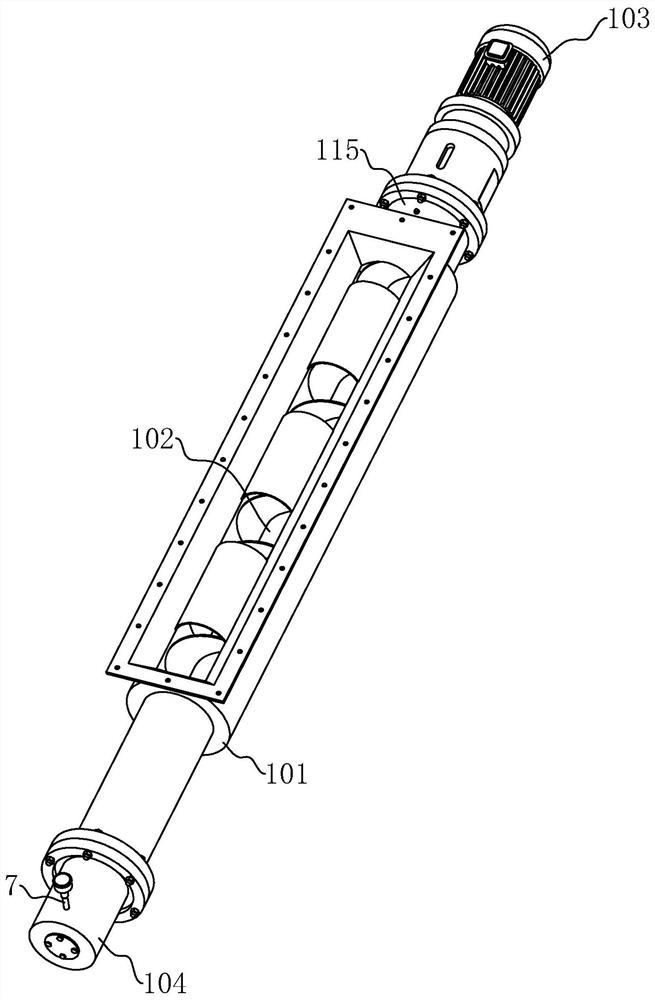
[0039] The embodiment of the present application discloses a screw conveyor, which is suitable for harsh environments with medium and low speed rotation. refer to figure 1 with figure 2 , the screw conveyor includes: a main casing 101, a screw body 102 and a power source 103, the screw body 102 is rotatably installed in the main casing 101 and its two ends protrude from the two ends of the main casing 101, and one end of the screw body 102 is connected with the power source 103 , the power source 103 drives the screw body 102 to rotate, the power source 103 is specifically a driving motor, and the screw body 102 is specifically composed of a cylindrical shaft and a helical blade spirally arranged on the outer peripheral wall of the cylindrical shaft.

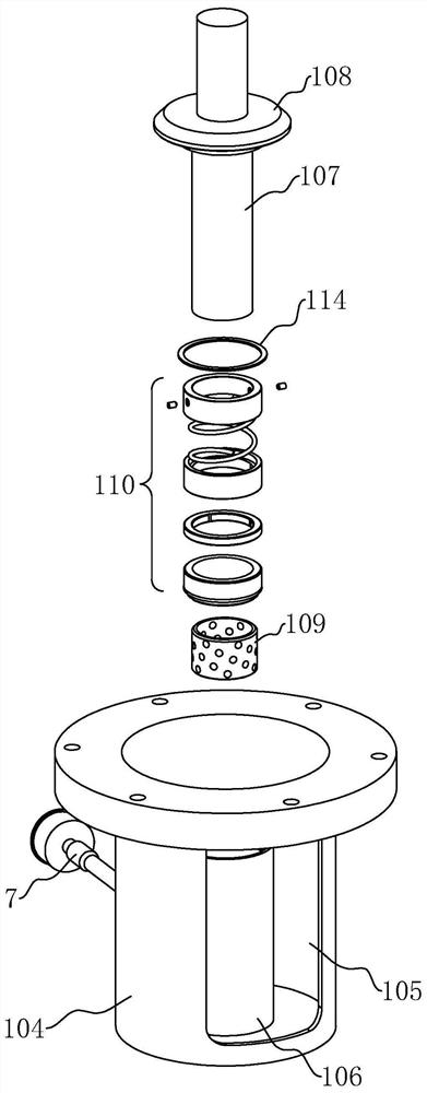
[0040] The end of the main casing 101 away from the power source 103 is fixedly installed with a tail casing 104, and the connect...


PUM


Abstract

The invention relates to a spiral conveyor. The spiral conveyor comprises a main machine shell, a spiral body and a power source, the spiral body is arranged in the main machine shell in a rotating mode, one end of the spiral body is connected to the power source, the power source drives the spiral body to rotate, a tail end shell is fixedly arranged at the end, away from the power source, of the main machine shell, the end, close to the main machine shell, of the tail end shell is open and communicates with the interior of the main machine shell, a discharging port is formed in the peripheral side of the tail end shell, a mounting cylinder is fixedly arranged in the tail end shell, a rotating shaft is fixedly arranged at the end, away from the power source, of the spiral body, a mounting cavity is formed in the mounting cylinder, an opening of the mounting cavity faces the spiral body, one part of the rotating shaft is inserted into the mounting cavity, a sealing ring is arranged on the rotating shaft and seals the opening of the mounting cavity, a self-lubricating structure is arranged between the rotating shaft and the mounting cylinder, and the self-lubricating structure is located between the outer circumferential wall of the rotating shaft and the inner circumferential wall of the mounting cavity. The spiral conveyor has the advantages of being capable of achieving the self-lubricating function, better in sealing performance, capable of almost achieving the maintenance-free effect and longer in service life.

Description

technical field [0001] The present application relates to the technical field of feeding mechanical equipment, in particular to a screw conveyor. Background technique [0002] The screw conveyor is a kind of machine that uses the motor to drive the screw to rotate and push the material to achieve the purpose of conveying. [0003] Ashing screw conveyor is a kind of screw conveyor. Ashing screw conveyor is the main auxiliary equipment of dry distillation process in the ammonia-soda alkali production process. Lime powder is successfully fed into the pre-ash bucket, and the tail outlet of the ash-adding screw conveyor must extend into the inside of the pre-ash bucket. The working environment conditions of the ash-adding screw conveyor in the bucket are: the temperature at the top is 90-95°C The preheated mother liquor is sprayed on the tail bearing parts, and there is a large amount of steam and ammonia mixed gas in the gas phase area. [0004] In view of the above-mentioned ...

Claims


Application Information

Patent Timeline
IPC IPC(8): B65G33/14B65G33/24B65G45/02
CPCB65G33/14B65G33/24B65G45/02
Inventor 刘成华蔡春芝
Owner 武汉宇格电力设备有限公司
Why Eureka
Try Eureka