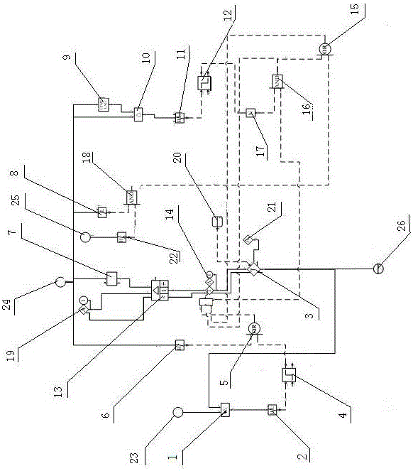
Denitration automatic regulating loop device
An automatic adjustment and loop technology, applied in the direction of electric controllers, separation methods, controllers with specific characteristics, etc., can solve the problems of inability to input, interference of denitration automatic adjustment, and inability to input adjustment loops, to ensure efficiency and quality, The effect of preventing overshoot
- Summary
- Abstract
- Description
- Claims
- Application Information
AI Technical Summary
Problems solved by technology
Method used
Image
Examples
Embodiment 1
[0023] A denitrification automatic adjustment circuit device, which consists of four parts: an automatic switch manual logic function circuit part; a normal adjustment function circuit part; a prohibition increase prohibition reduction function circuit part;
Embodiment 2
[0025]According to the denitrification automatic adjustment circuit device described in embodiment 1, it is characterized in that: the part of the manual switching logic circuit includes: a comparison device-1, and the two input terminals of the comparison device-1 are respectively fed back to the adjustment gate The signal 23 is connected to the output terminal of the analog quantity switching selection device 3, and accepts the output command of the adjustment gate feedback signal 23 and the analog quantity switching selection device 3, and the comparison device 1 calculates the deviation between the two, and the calculation result is used as the output command, and its output End is connected with the input end of high and low limit device-2; High and low limit device-2, the input end of described high and low limit device-2 is connected with the output end of comparison device-1, accepts the output command of comparison device-1, and with High and low limit value comparison...
Embodiment 3
[0027] According to the denitrification automatic adjustment circuit device described in embodiment 1 or 2, the normal adjustment function part includes: a set value device 19, and the set value device 19 accepts the manual set value signal of the operator, and outputs Terminal is connected with one of the input terminal S terminals of PID regulator 13; Lag device one 7, described lag device one 7 is connected with the modulated signal 24, accepts the modulated signal, and performs lag processing to the signal, its output terminal is connected with another input terminal P terminal of PID regulator 13; PID regulator 13, two input terminals S terminal and P terminal of described PID regulator 13 are respectively connected with setting value device 19 and hysteresis device one 7 , and accept the output command of the setting value device 19 and the hysteresis device one 7, output the control command after corresponding PID calculation according to the deviation of the two, and it...
PUM
 Abstract
Description
Claims
Application Information
 - R&D
- Intellectual Property
- Life Sciences
- Materials
- Tech Scout
- Unparalleled Data Quality
- Higher Quality Content
- 60% Fewer Hallucinations
Browse by: Latest US Patents, China's latest patents, Technical Efficacy Thesaurus, Application Domain, Technology Topic, Popular Technical Reports.
© 2025 PatSnap. All rights reserved.Legal|Privacy policy|Modern Slavery Act Transparency Statement|Sitemap|About US| Contact US: help@patsnap.com

