[0017] The technical solution of this patent will be described in further detail below in conjunction with specific embodiments.
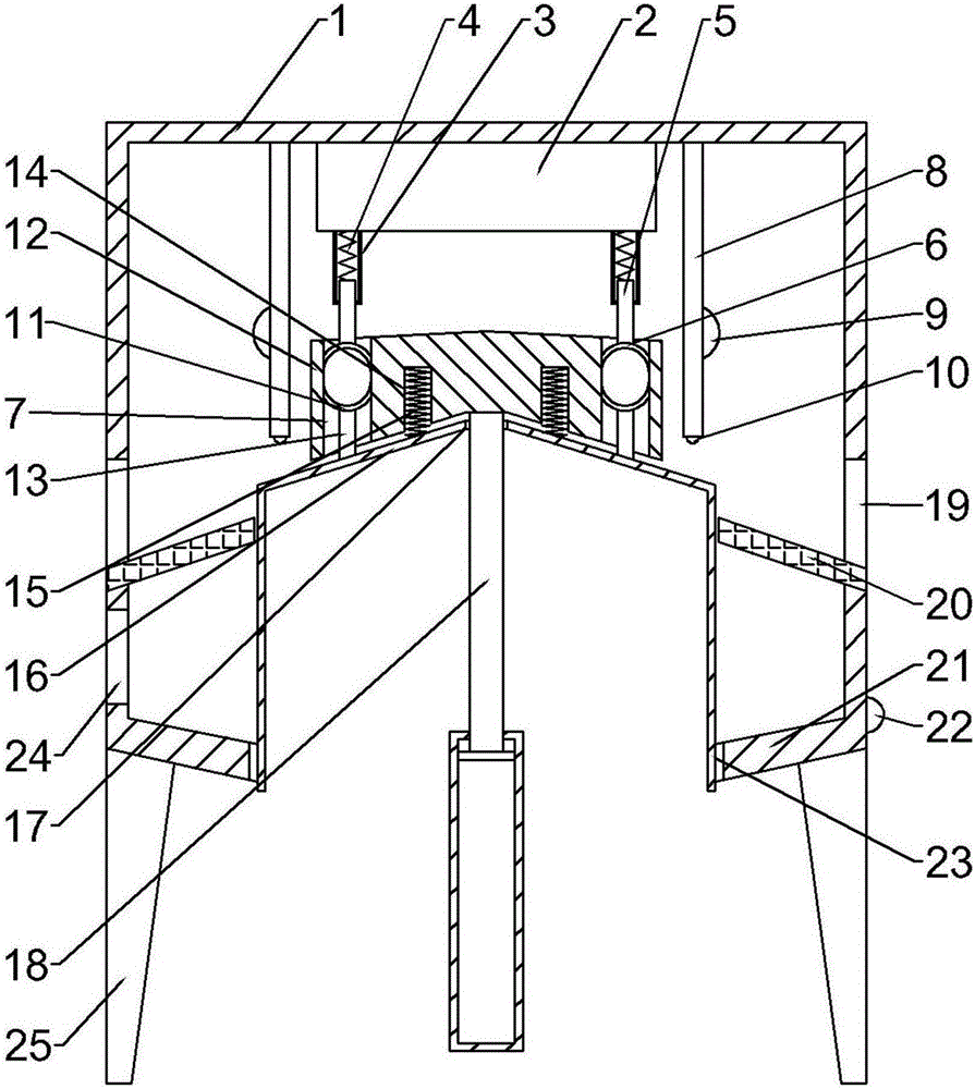
[0018] See figure 1 , A molding equipment for the production of organic fertilizer, comprising a housing 1, a fixed block 2 is fixedly connected to the upper part of the housing 1, and a plurality of outer sleeves 3 are fixedly connected to the lower part of the fixed block 2. The outer sleeve 3 The upper connecting rod 5 is sleeved inside, and the upper connecting rod 5 is fixedly connected with a first spring 4, the upper end of the first spring 4 is fixedly connected with the inner bottom of the outer sleeve 3, and the lower end of the upper connecting rod 5 is fixedly connected with Upper mold 6;
[0019] The fixing block 2 is symmetrically fixedly connected with a top rod 8 on both sides, a connecting block 12 is provided in the middle of the housing 1, and the lower surface of the connecting block 12 is concave, and a plurality of through holes 7 are opened on the connecting block 12. The through hole 7 is located directly below the upper mold 6. A first guide plate 16 is provided under the connecting block 12. The first guide plate 16 is conical. The first guide plate 16 fits with the lower surface of the connecting block 12, and the top center of the first guide plate 16 A rod hole 17 is provided. The rod hole 17 is sleeved with an electric telescopic rod 18, and the electric telescopic rod 18 passes through the rod hole 17 and is fixedly connected to the connecting block 12. The lower surface of the first guide plate 16 is fixedly connected with a number of lower connecting rods. The lower connecting rod 13 is sleeved in the through hole 7. The lower connecting rod 13 is fixedly connected to the lower mold 11, and the lower surface of the connecting block 13 is symmetrically provided with two connecting grooves 14. The connecting grooves 14 The inner sleeve is provided with a second spring 15, and the lower end of the second spring 15 is fixedly connected with the first guide plate 16;
[0020] A second guide plate 20 is fixedly connected to the middle of the housing 1, and the second guide plate 20 is inclined to the outside. The bottom of the housing 1 is fixedly connected to a third guide plate 21 which is inclined to the inside. An enclosure 23 is sleeved in the middle of the three guide plate 21, the enclosure 23 is cylindrical, and the outer diameter of the enclosure 23 is the same as the outer diameter of the first guide plate 16, and the enclosure 23 is fixed on the lower surface of the first guide plate 16;
[0021] Put the raw material to be processed into the housing 1 through the feed port 24, then start the start switch 22, the electric telescopic rod 18 moves up and down, when the electric telescopic rod 18 is at the bottom, the first guide plate 16 and the third guide plate 21 Level, the raw material in the device rolls into the through hole 7 of the connecting block 12, the raw material entering the through hole 7 is supported by the lower mold 11, and then the electric telescopic rod 18 moves upwards, the connecting block 12 and the first guide plate 16 are both upward When moving and moving, the excess raw materials on the upper surface of the connecting block 12 will roll off, and the raw materials inside the housing 1 will be blocked by the enclosure 23 and will not fall. Continue to move upward, and the upper mold 6 enters the through hole 7 to start pressing the raw materials. The raw material is formed. When the first guide plate 16 is blocked by the push rods 8 on both sides, the connecting block 12 continues to move up, the lower mold 11 and the first guide plate 16 stop moving up, the contact switch 10 is pressed so that the vibration motor 9 is opened, and the first guide plate 16 is vibrated, the connecting block 12 continues to move upward, the lower mold 11 moves out of the through hole 7, and then the raw material falls on the second guide plate 20 under the vibration of the vibration motor 9, and then flows out along the second guide plate 20. The material opening 19 can be collected. When the raw materials are all dropped, the electric telescopic rod 18 goes down, so that the connecting block 12 goes down, and finally comes into contact with the first guide plate 16 and goes down to the initial position, reciprocating.
[0022] A contact switch 10 is fixedly connected to the lower end of the top rod 8, a vibration motor 9 is fixedly connected to both sides of the top rod 8, and the vibration motor 9 is electrically connected to the contact switch 10.
[0023] The first guide plate 16 and the second guide plate 20 have the same inclination angle.
[0024] A feed port 24 is opened on the left side of the housing 1, and the feed port 24 is located between the second guide plate 20 and the third guide plate 21.
[0025] A bracket 25 is fixedly connected to the bottom of the housing 1.
[0026] A discharge port 19 is symmetrically provided on both sides of the housing 1, and the discharge port 19 is located above the second guide plate 20.
[0027] A start switch 22 is fixedly connected to the right side of the housing 1.
[0028] The upper surface of the connecting block 12 is conical, and the upper surface of the connecting block 12 is inclined outward.
[0029] The working principle of the present invention is: the raw material to be processed and formed is added into the housing 1 through the feed port 24, and then the start switch 22 is activated, and the electric telescopic rod 18 moves up and down. When the electric telescopic rod 18 is at the bottom, the first The guide plate 16 is flush with the third guide plate 21, the raw material in the device rolls into the through hole 7 of the connecting block 12, the raw material entering the through hole 7 is supported by the lower mold 11, and then the electric telescopic rod 18 moves upward, and the connecting block 12 Both the first guide plate 16 and the first guide plate 16 move upwards. During the movement, the excess raw materials on the upper surface of the connecting block 12 will roll off, and the raw materials inside the housing 1 will be blocked by the enclosure plate 23 and will not fall. The raw material starts to be pressed in the hole 7 so that the raw material is formed. When the first guide plate 16 is blocked by the push rods 8 on both sides, the connecting block 12 continues to move upward, the lower mold 11 and the first guide plate 16 stop moving upward, and the contact switch 10 is forced to vibrate The motor 9 is turned on, the first guide plate 16 is vibrated, the connecting block 12 continues to move upward, the lower mold 11 moves out of the through hole 7, and then the raw material falls on the second guide plate 20 under the vibration of the vibration motor 9, and then moves along the first guide plate 20. The second guide plate 20 flows out and can be collected at the discharge port 19. When the raw materials are all dropped, the electric telescopic rod 18 goes down, causing the connecting block 12 to go down, and finally contacts the first guide plate 16 to go down to the initial position and reciprocate.
[0030] For those skilled in the art, it is obvious that the present invention is not limited to the details of the foregoing exemplary embodiments, and the present invention can be implemented in other specific forms without departing from the spirit or basic characteristics of the present invention. Therefore, from any point of view, the embodiments should be regarded as exemplary and non-limiting. The scope of the present invention is defined by the appended claims rather than the foregoing description, and therefore it is intended to fall within the claims. All changes within the meaning and scope of the equivalent elements of are included in the present invention. Any reference signs in the claims should not be regarded as limiting the claims involved.
[0031] In addition, it should be understood that although this specification is described in accordance with the implementation manners, not each implementation manner only includes an independent technical solution. This narration in the specification is only for clarity, and those skilled in the art should consider the specification as a whole The technical solutions in the embodiments can also be appropriately combined to form other implementations that can be understood by those skilled in the art.