Centralized-driven pulling-straightening device with closely-arranged rollers and continuous casting machine adopting same

A technology of centralized drive and continuous casting machine, applied in the field of iron and steel continuous casting machine, can solve the problems of complex sector structure, large floor space, heavy equipment weight, etc., and achieve the effect of reducing equipment weight, simplifying equipment, and simplifying structure.

Inactive Publication Date: 2017-03-22
SHANGHAI YAOQIN METALLURGY EQUIP TECHN
View PDF6 Cites 0 Cited by
  • Summary
  • Abstract
  • Description
  • Claims
  • Application Information

AI Technical Summary

Problems solved by technology

[0003] In the mode of driving through the motor reducer in multiple sectors, it is necessary to set the driving roller in multiple sectors and use a universal coupling to connect the motor reducer and the driving roller. Therefore, this mode leads to a complex structure of the sector. The weight of the equipment is heavy, and the guide rail needs to be pulled out during maintenance, which occupies a large area and cannot be applied to a multi-strand continuous casting machine with more than two strands

Method used


Image

  • Centralized-driven pulling-straightening device with closely-arranged rollers and continuous casting machine adopting same
  • Centralized-driven pulling-straightening device with closely-arranged rollers and continuous casting machine adopting same
  • Centralized-driven pulling-straightening device with closely-arranged rollers and continuous casting machine adopting same

Examples


Embodiment Construction

[0031] Below in conjunction with specific embodiment, further set forth the present invention, should be understood that these embodiments are only used to illustrate the present invention and are not intended to limit the scope of the present invention, in addition should be understood that, after having read the content that the present invention expresses, those skilled in the art Various changes or modifications can be made to the present invention, and various changes or modifications of these equivalent forms also fall within the scope defined by the appended claims of this application.

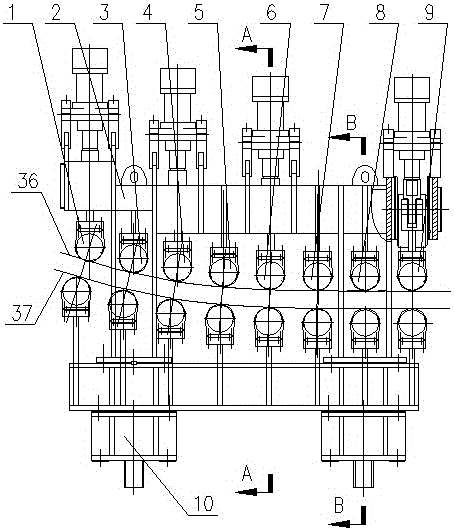
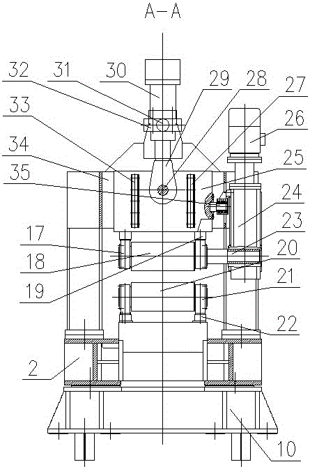
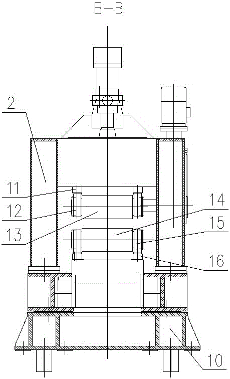
[0032] see figure 1 , figure 2 , image 3 , an embodiment of the tension leveling device driven by densely packed rollers of the present invention, which mainly consists of a frame (2), four pairs of casting machine driving rollers (1, 4, 6, 9), four pairs of clamping rollers (3, 5, 7, 8), the roll system composed of four pairs of caster driving rolls (1, 4, 6, 9) and four pairs of c...


PUM


Abstract

The invention provides a centralized-driven pulling-straightening device with closely-arranged rollers. The centralized-driven pulling-straightening device is mainly composed of a rack, the multiple pairs of casting machine driving rollers and a plurality of pairs of clamping rollers. A roller system formed by the driving rollers and the clamping rollers covers and overlaps with roller layout curves of a straightening section and a horizontal section of a continuous casting machine roller system. Each clamping roller is arranged between the two corresponding adjacent pairs of driving rollers. A closely-arranged mode is adopted for the roller distances between the adjacent rollers. The driving rollers and the clamping rollers are arranged in the rack according to the roller layout curves of the straightening section and the horizontal section of the continuous casting machine. Upper roller bodies of the driving rollers are lifting rollers, and lower roller bodies of the driving rollers are fixed rollers. Upper roller bodies and lower roller bodies of the clamping rollers are fixed rollers. By adoption of centralized-driven pulling-straightening device, the structure of a fan-shaped section of the continuous casting machine is simplified, the roller system lengths of the straightening section and the horizontal section are fully utilized, and therefore it is ensured that the bulging of a continuous casting is controlled in a reasonable range while the capacity of the continuous casting machine is effectively increased, and when the casting machine is limited by space, the basic radius of the casting machine can be allowed to be smaller.

Description

technical field [0001] The invention relates to a continuous casting machine for iron and steel, in particular to a tension leveling device driven intensively by close-packed rollers and a continuous casting machine using the device. Background technique [0002] In the continuous casting process of an arc or straight arc continuous casting machine, due to the frictional resistance of the clamping rollers to the slab and the large reaction force in the bending and straightening process, a drive system is required to ensure continuous casting The billet is pulled out smoothly from the segment; at present, the slab continuous casting machine generally adopts the mode of decentralized driving through the motor reducer in multiple segments due to the dense arrangement of rolls; Generally, multiple tension levelers are used for driving; these two modes have certain advantages and disadvantages. [0003] In the mode of driving through the motor reducer in multiple sectors, it is ...

Claims


Application Information

Patent Timeline
IPC IPC(8): B22D11/128B22D11/12
CPCB22D11/1287B22D11/1226
Inventor 张生宁张焕鑫刘雯
Owner SHANGHAI YAOQIN METALLURGY EQUIP TECHN
Why Eureka
Try Eureka