Laser additive manufacturing forming method of titanium alloy thin-walled component

A thin-walled component and laser additive technology, applied in the directions of additive manufacturing, additive processing, and process efficiency improvement, can solve the problems of limited casting precision, long development cycle, and difficult control of casting quality, and achieve a shortened manufacturing cycle. Effect

Inactive Publication Date: 2017-03-22
BEIJING SATELLITE MFG FACTORY
View PDF9 Cites 18 Cited by
  • Summary
  • Abstract
  • Description
  • Claims
  • Application Information

AI Technical Summary

Problems solved by technology

[0004] The technical problem to be solved by the present invention is: to overcome the disadvantages of the traditional manufacturing process, such as difficult control of casting quality, long development cycle, and limited casting precision, to provide a laser additive manufacturing forming method for titanium alloy thin-walled components, which can solve the problem of dimensional stability. question

Method used


Image

  • Laser additive manufacturing forming method of titanium alloy thin-walled component
  • Laser additive manufacturing forming method of titanium alloy thin-walled component
  • Laser additive manufacturing forming method of titanium alloy thin-walled component

Examples


Embodiment 1

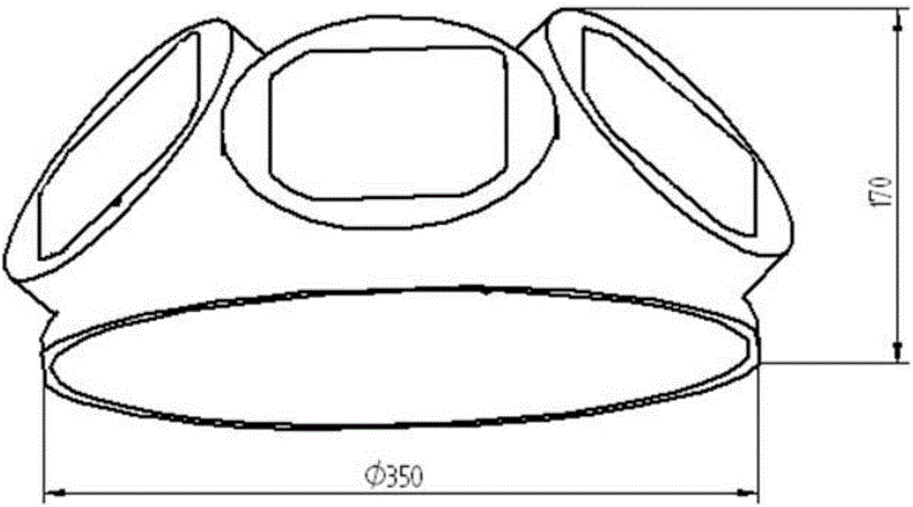
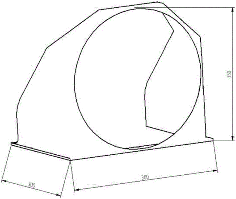
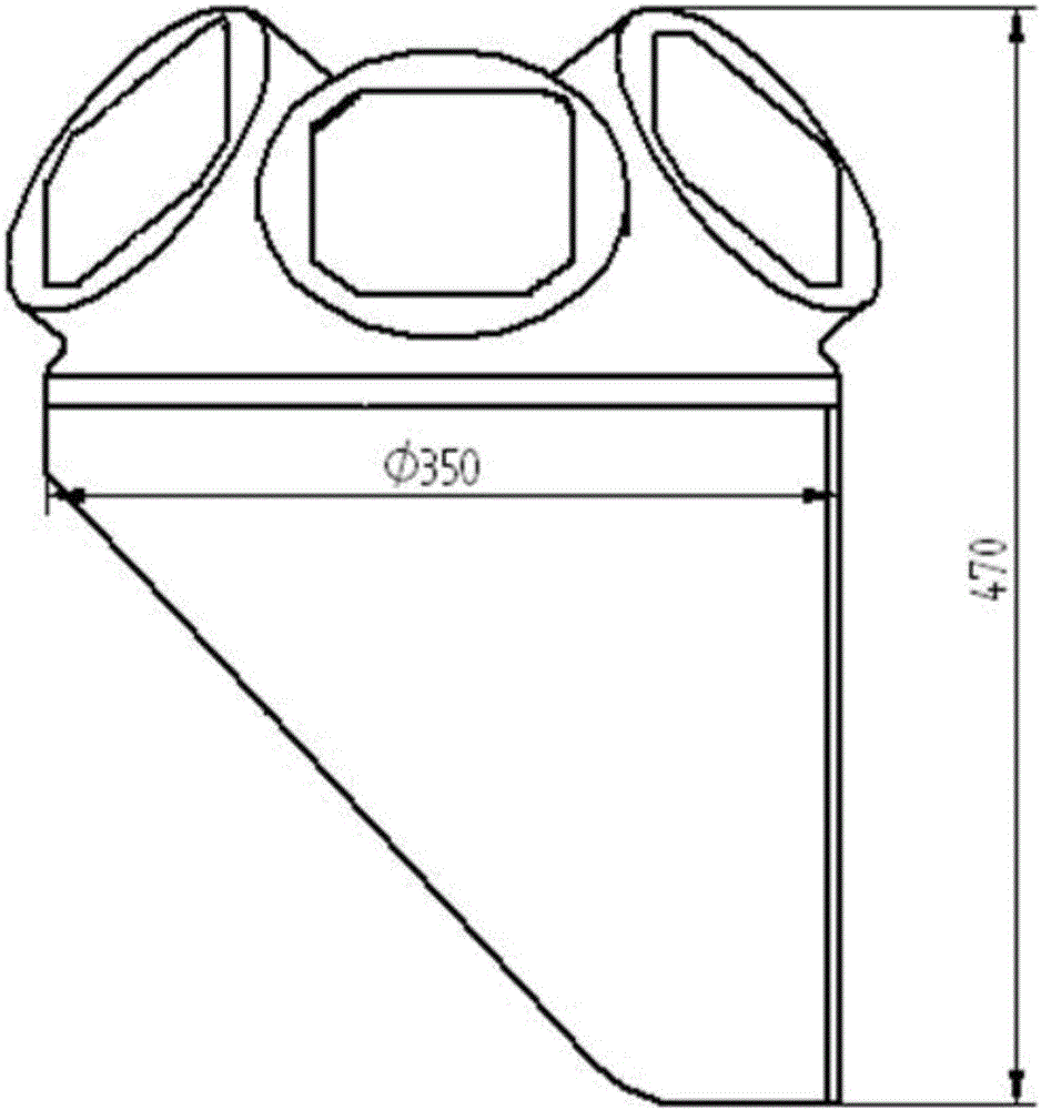
[0030] A laser additive manufacturing forming method for titanium alloy thin-walled components, such as Figure 1~3 As shown, the titanium alloy thin-walled member includes a support cylinder composed of three cylinders and a plate-shaped bottom bracket. The steps of the method include:

[0031] (1) The bottom bracket and the support cylinder are respectively formed by the method of laser selective melting and forming. The process parameters during forming are: laser power is 350W, spot diameter is 0.08mm, scanning speed is 1100mm / s, and powder coating thickness is 0.03mm ;

[0032] (2) Carry out heat treatment on the bottom bracket with base plate and support and support tube with base plate and support at the same time. The process parameters of heat treatment are: temperature is 800°C, holding time is 2.5h, working pressure is 1×10 -3 Pa, cooling with the furnace after the heat preservation is over;

[0033] (3) Carry out wire cutting to the heat-treated bottom bracket an...

Embodiment 2

[0038] (1) The bottom bracket and the support cylinder are respectively formed by laser selective melting and forming. The process parameters during forming are: laser power 360W, spot diameter 0.07mm, scanning speed 1200mm / s, powder coating thickness 0.04mm ;

[0039] (2) Carry out heat treatment on the bottom bracket with base plate and support and the support cylinder with base plate and support at the same time. The process parameters of heat treatment are: temperature is 810°C, holding time is 2h, working pressure is 1×10 -3 Pa, cooling with the furnace after the heat preservation is over;

[0040] (3) Carry out wire cutting to the heat-treated bottom bracket and the support tube, remove the substrate, and obtain only the bottom bracket and the support tube with support;

[0041] (4) remove the support of the bottom bracket and the support cylinder, obtain the bottom bracket and the support cylinder, and polish and sandblast the surface of the bottom bracket and the supp...


PUM

PropertyMeasurementUnit
thicknessaaaaaaaaaa
diameteraaaaaaaaaa
tensile strengthaaaaaaaaaa

Abstract

The invention relates to a laser additive manufacturing forming method of a titanium alloy thin-walled component, in particular to a preparing method of a multi-branch thin-walled titanium alloy structure and belongs to the technical field of titanium alloy structural machining and molding. The preparing method is the structural preparing method based on a selective laser melting forming and laser cladding technology. According to the thin wall, the titanium alloy structure with the thickness of the titanium alloy not larger than 5mm and particularly the wall thickness ranging from 2 mm to 4 mm is formed. The titanium alloy complex thin-walled component obtained through the method has the 4mm wall thickness, and the 0.1mm / 100mm size precision, and the manufacturing period is shortened by 50%.

Description

technical field [0001] The invention relates to a method for laser additive manufacturing of titanium alloy thin-walled components, in particular to a method for preparing a multi-branched, thin-walled titanium alloy structure, which is a structure preparation method based on laser selective melting and laser cladding technology. The thin-walled titanium alloy refers to the thickness of the titanium alloy not greater than 5mm, especially suitable for the forming of the titanium alloy structure with a wall thickness of 2-4mm, and belongs to the technical field of processing and forming of the titanium alloy structure. Background technique [0002] A large number of complex thin-walled and lightweight titanium alloy secondary load-bearing structural parts are used on the spacecraft. The main features include: thin-walled structure, complex shape, various types, high dimensional stability and mechanical performance requirements, product installation surface space angle and other...

Claims


Application Information

Patent Timeline
Patent Type & Authority Applications(China)
IPC IPC(8): B22F3/105B22F3/24B22F5/10C22F1/18B33Y10/00B33Y80/00
CPCC22F1/183B22F3/24B22F5/10B33Y10/00B33Y80/00B22F2003/248B22F10/00B22F10/66B22F10/64B22F10/36B22F10/47Y02P10/25
Inventor 巩维艳王哲王震陈材陈怡蒋疆祁俊峰
Owner BEIJING SATELLITE MFG FACTORY
Why Eureka
Try Eureka