Movable wharf

A wharf and engine technology, applied in the field of mobile wharf, can solve the problems of increasing soil grabbing and fixing effects, not having anti-landing boards, and not being able to resist strong winds, so as to prevent detachment from fixed pillars, reduce direct damage, and reduce resistance.

Active Publication Date: 2017-03-22
ZHEJIANG OCEAN UNIV
View PDF7 Cites 9 Cited by
  • Summary
  • Abstract
  • Description
  • Claims
  • Application Information

AI Technical Summary

Problems solved by technology

[0003] In the prior art, commonly used landing boards are generally unable to resist strong winds, and at the same time only have a pair of hooks, the fixing effect is not good, and it is easy to cause loosening when the wind and waves are strong
[0004] For example, the application number is "200520098073.5", and the invention name is "Mobile Wharf", which does not have a landing board against various bad weather, and does not have an anchor that can increase the effect of grabbing soil and fixing it.

Method used


Image

  • Movable wharf
  • Movable wharf
  • Movable wharf

Examples


Embodiment 1

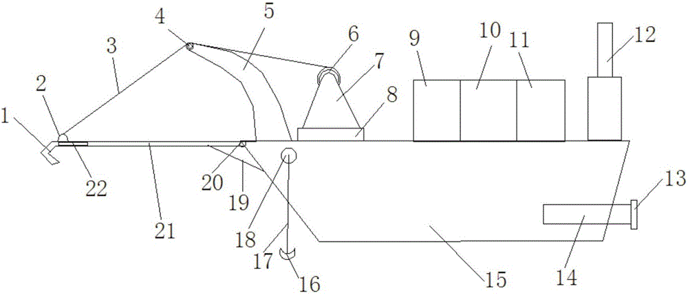
[0023] Example one: such as figure 1 As shown, the present invention includes a hull 15 and an engine 14 and a propeller 13 arranged inside the hull 15. One end of the hull 15 is provided with a landing plate 21 through a rotating connector 20, and an arc-shaped fixing member is provided on the upper surface of the landing plate 21 2. A front hook body 1 is provided at the end of the landing plate 21, and a side hook body 22 is provided on the side of the landing plate 21. The upper surface of the hull 15 is provided with a supporting bending rod 5, a winch 6, a controller 9, a generator 10, and a fuel tank. 11 and a signal transceiving device 12, a support block 4 is arranged on the top of the support bending rod 5, the support block 4 is arranged on the bow of the ship close to the landing board 21, the winch 6 is provided with a draw rope 3, and the draw The rope 3 is connected to the arc-shaped fixing member 2 by the hoist 6, the draw rope 3 is in contact with the top of the...

Embodiment 2

[0025] Embodiment two: such as figure 1 As shown, the present invention includes a hull 15 and an engine 14 and a propeller 13 arranged inside the hull 15. One end of the hull 15 is provided with a landing plate 21 through a rotating connector 20, and an arc-shaped fixing member is provided on the upper surface of the landing plate 21 2. A front hook body 1 is provided at the end of the landing plate 21, and a side hook body 22 is provided on the side of the landing plate 21. The upper surface of the hull 15 is provided with a supporting bending rod 5, a winch 6, a controller 9, a generator 10, and a fuel tank. 11 and a signal transceiving device 12, a support block 4 is arranged on the top of the support bending rod 5, the support block 4 is arranged on the bow of the ship close to the landing board 21, the winch 6 is provided with a draw rope 3, and the draw The rope 3 is connected to the arc-shaped fixing member 2 by the hoist 6, the draw rope 3 is in contact with the top of ...

Embodiment 3

[0029] Example three: such as figure 1 As shown, the present invention includes a hull 15 and an engine 14 and a propeller 13 arranged inside the hull 15. One end of the hull 15 is provided with a landing plate 21 through a rotating connector 20, and an arc-shaped fixing member is provided on the upper surface of the landing plate 21 2. A front hook body 1 is provided at the end of the landing plate 21, and a side hook body 22 is provided on the side of the landing plate 21. The upper surface of the hull 15 is provided with a supporting bending rod 5, a winch 6, a controller 9, a generator 10, and a fuel tank. 11 and a signal transceiving device 12, a support block 4 is arranged on the top of the support bending rod 5, the support block 4 is arranged on the bow of the ship close to the landing board 21, the winch 6 is provided with a draw rope 3, and the draw The rope 3 is connected to the arc-shaped fixing member 2 by the hoist 6, the draw rope 3 is in contact with the top of t...


PUM


Abstract

The invention discloses a movable wharf. The movable wharf comprises a ship body, an engine and a propeller, and the engine and the propeller are arranged in the ship body. One end of the ship body is provided with a landing plate through a rotary connecting part. An arc-shaped fixing part is arranged on the upper surface of the landing plate. A front face hook body is arranged at the tail end of the landing plate. A side face hook body is arranged on the side face of the landing plate. A supporting curved bar, a winch, a controller, an electric generator, a fuel tank and a signal receiving and transmitting device are arranged on the upper surface of the ship body. A supporting block is arranged at the top of the supporting curved bar and arranged on the part, close to the landing plate, of the nose. The winch is provided with a stay cord. The stay cord is connected with the arc-shaped fixing part through the winch and makes contact with the top of the supporting block. A groove is formed in the top of the supporting block. The stay cord is arranged in the groove in the top of the supporting block. A fixing fulcrum bar is arranged on the side face of the ship body and connected with an anchor through a rope. The movable wharf has the characteristics of being capable of transporting lots of persons and materials and resisting severe weathers and good in fixing effect.

Description

Technical field [0001] The invention belongs to the technical field of ship construction, and particularly relates to a mobile dock that can not only transport a large number of people and materials, but also has a landing board that can resist bad weather and has a better fixed effect. Background technique [0002] The existing fixed docks have fixed buildings, and most of these buildings are hydraulic constructions, which have long construction periods and high costs. In special circumstances such as earthquakes, tsunamis, and wars, the wharf and its auxiliary buildings and equipment are easily damaged. Difficulties are often encountered when transporting people and materials. Helicopters and landing craft are usually used for transportation, and their load capacity is not large, which is far from meeting the needs of mass transportation of personnel and materials. Therefore, it is the invention of the present invention to invent an intermediary platform that can directly rea...

Claims


Application Information

Patent Timeline
Patent Type & Authority Applications(China)
IPC IPC(8): B63B35/44B63B27/14B63B21/20B63B21/26B63B21/04
CPCB63B21/04B63B21/20B63B21/26B63B27/14B63B35/44B63B2021/203
Inventor 倪云林
Owner ZHEJIANG OCEAN UNIV
Why Eureka
Try Eureka