
Wood plate airing and rod putting machine

A technology for the board and wood industry, which is applied in the field of wood board drying and laying machines, can solve the problems of large labor and low efficiency of workers, and achieve the effect of improving safety.

Active Publication Date: 2017-03-22
孟凡科
View PDF10 Cites 2 Cited by
  • Summary
  • Abstract
  • Description
  • Claims
  • Application Information

AI Technical Summary

Problems solved by technology

[0002] At present, for the wood panel processing industry, in the daily production of wood panels, due to the differences in the growth environment of wood, the rotary-cut veneer often has scars and some unnatural raised holes. etc. In the daily production process, the traditional method of applying wood putty and then polishing is generally used to repair the scars for these problems that affect processing. For the veneer after applying the putty material, the board needs to be dried to make the surface of the board The putty material is dried naturally or with hot air. In order to save the time of drying or drying, the board needs to be separated and separated by wooden strips or square rods during the drying or drying process to prevent the putty material being applied. Adhesion between the boards, but this action of putting wooden strips or square rods needs to be done manually. When the boards are scraped and coated with putty by the putty scraper, 2-3 people are required to put the square rods on the boards, which requires a lot of labor. low production efficiency

Method used


Image

  • Wood plate airing and rod putting machine
  • Wood plate airing and rod putting machine
  • Wood plate airing and rod putting machine

Examples

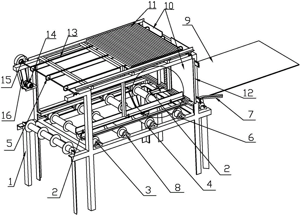
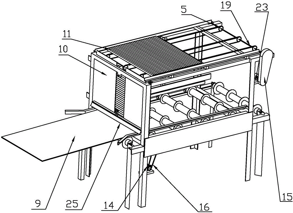
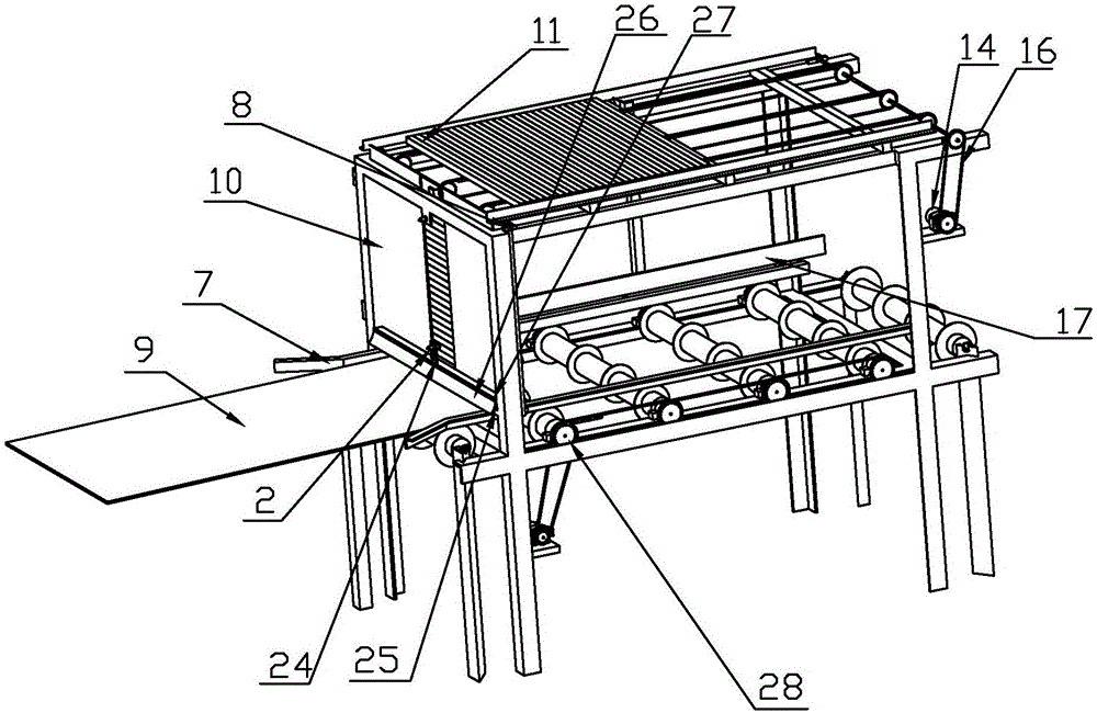

Embodiment Construction

[0024] For the convenience of those skilled in the art to understand, the following in conjunction with the attached Figure 1-5 , to further specifically describe the technical solution of the present invention.

[0025] A wood panel drying rod machine, including a frame 1, a photoelectric sensor 2, a roller 3, a placement board 10, a square rod 11, a chain support board 13, a sensor placement rack 17, a connecting rod shaft 19, a cylinder 20, a discharge Push plate 21, the top of the frame 1 is provided with several bearing blocks 6, the two sides of the top of the frame 1 are respectively provided with a connecting rod shaft 19, and one end of the connecting rod shaft 19 is provided with a sprocket 5, and the sprocket 5 Link to each other with the motor 14 of lower side by chain 16, described motor 14 is arranged on the motor support plate 23, and motor support plate 23 is welded on the frame 1, and described motor 14 provides power for chain 16, and described connecting ro...


PUM


Abstract

The invention discloses a wood plate airing and rod putting machine. The wood plate airing and rod putting machine comprises a rack, photoelectric sensors, rollers, placing plates, square rods, chain support plates, a sensor placing frame, connecting rod shafts, an air cylinder and a discharge push plate, wherein the connecting rod shafts are respectively arranged on both sides of the top of the rack, a plurality of chain wheels are arranged on the connecting rod shafts, the chain support plates are arranged on the lower sides of chains, the square rods are placed on the upper sides of the chains, sensor installation pieces are arranged on the upper and lower sides of the rack between the placing plates, the photoelectric sensors are arranged on the sensor installation pieces, a rod outlet is formed in the lower sides of the placing plates, a baffle is arranged on one side of the rod outlet, the discharge push plate is arranged on one end of the air cylinder, a plurality of photoelectric sensors are arranged on the sensor placing frame, a plurality of height increasing rings are arranged on the rollers, and double rows of chain wheels are arranged on one side of the rollers. The wood plate airing and rod putting machine is used for conveying plates, and then the square rods automatically fall by a pushing mechanism, so that the rods are uniformly placed on the plates.

Description

technical field [0001] The invention belongs to the technical field of wood board processing, and in particular relates to a wood board air-drying pole-releasing machine. Background technique [0002] At present, for the wood panel processing industry, in the daily production of wood panels, due to the differences in the growth environment of wood, the rotary-cut veneer often has scars and some unnatural raised holes. etc. In the daily production process, the traditional method of applying wood putty and then polishing is generally used to repair the scars for these problems that affect processing. For the veneer after applying the putty material, it is necessary to dry the board to make the surface of the board The putty material is dried naturally or with hot air. In order to save the drying or drying time, the board needs to be separated and separated by wooden strips or square rods during the drying or drying process to prevent the putty material from being applied. Adh...

Claims


Application Information

Patent Timeline
Patent Type & Authority Applications(China)
IPC IPC(8): B65G57/00B27G1/00
CPCB27G1/00B65G57/005B65G2201/0282
Inventor 孟凡科
Owner 孟凡科
Learn More