Tubular oil and water separation device

An oil-water separation device, a tubular technology, applied in separation methods, liquid separation, grease/oily substance/floating matter removal devices, etc., can solve the problems of high requirements for processing materials, large equipment volume, and high equipment cost, and achieve equipment manufacturing. Low requirements, high separation effect, low equipment cost

Active Publication Date: 2017-03-22
MORIMATSU (JIANGSU) HEAVY IND CO LTD
View PDF17 Cites 7 Cited by
  • Summary
  • Abstract
  • Description
  • Claims
  • Application Information

AI Technical Summary

Problems solved by technology

[0003] The technical problem to be solved by the present invention is to provide a tubular oil-water separation device, which can solve the problems of bulky equipment, low separation capacity, high equipment cost, and high requirements for materials to be processed.

Method used


Image

  • Tubular oil and water separation device

Examples


Embodiment Construction

[0016] The following examples can enable those skilled in the art to understand the present invention more comprehensively, but the present invention is not limited to the scope of the described examples.

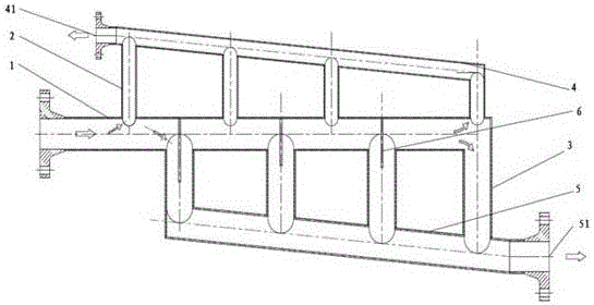
[0017] Such as figure 1 A tubular oil-water separation device shown includes a connecting pipe 1, an oil phase flotation tube group 2, a water phase settling tube group 3, an oil collecting tube 4 and a water collecting tube 5; the oil phase flotation tube group 2 and the water phase settling The axes of the tube groups 3 are parallel to each other, and the oil phase flotation tube groups 2 and the water phase settling tube groups 3 are arranged alternately on the connecting pipe 1 .

[0018] One end of the connecting pipe 1 is closed, one end is open, and the opening end is provided with a flange; the side wall of the connecting pipe 1 along the axial direction is respectively provided with an oil phase flotation tube hole group and a water phase settling tube hole group; ...


PUM

PropertyMeasurementUnit
angleaaaaaaaaaa

Abstract

The invention relates to a tubular oil and water separation device. The device is characterized by comprising a communicating tube, an oil phase flotation tube group, a water phase sedimentation tube group, an oil collecting tube and a water collecting tube. An oil and water mixed liquid is under the gravity effect while moving in the communicating tube, graded separation is performed according to specific characteristics of the mixed liquid, the moving path of large-particle oil drops in equipment is shortened, the stay time of small-particle oil drops is prolonged, so that the higher separation effect is realized, and the purposes of reduction of the size of the equipment and decrease of the production cost of the equipment are achieved. All parts are made of conventional materials in the industry, special machining and production requirements are not needed, and all the parts are reliable in use performance and have lower requirements for treated materials, so that the equipment has the lower production requirement and is low in production cost and wider in application range. The device is reasonable in structure, convenient to operate and use and reliable in performance.

Description

technical field [0001] The invention relates to the technical field of oil-water separation, in particular to a tubular oil-water separation device. Background technique [0002] With the continuous exploitation of oilfields, the water content in the oilfield production fluid has increased significantly, which has intensified the consumption of water treatment equipment in the oilfield industry; The higher and higher requirements have also increased the demand for oil and water treatment equipment. Traditional water treatment equipment has a large geometric volume or low oil-water separation treatment capacity, which cannot meet the requirements of regulations and standards technically; new membrane separation equipment and cyclone separation equipment have high manufacturing requirements and high equipment costs. , the requirements for processing materials are relatively high, which restricts its promotion and application scope to a certain extent. Contents of the invent...

Claims


Application Information

Patent Timeline
Patent Type & Authority Applications(China)
IPC IPC(8): C02F1/24C02F1/40B01D17/028B01D17/032C02F103/10
CPCB01D17/0211B01D17/0214C02F1/24C02F1/40C02F2103/10C02F2001/007
Inventor 陶旭鹏
Owner MORIMATSU (JIANGSU) HEAVY IND CO LTD
Why Eureka
Try Eureka