Column-supported-by-beam transfer beam with steel plate reinforced concrete shear walls arranged in adjacent spans

A steel plate concrete and steel plate shear wall technology, applied in the field of transfer beams, can solve problems such as insufficient shear resistance of steel concrete columns and sudden changes in bearing capacity, and achieve the effect of reducing impact and harmonizing building functions and structural systems

Active Publication Date: 2017-03-22
香港华艺设计顾问(深圳)有限公司
View PDF8 Cites 6 Cited by
  • Summary
  • Abstract
  • Description
  • Claims
  • Application Information

AI Technical Summary

Problems solved by technology

[0004] The technical problem to be solved by the present invention is to provide a technology for transfer beams with steel plate concrete shear walls adjacent to the span, so that it can effectively solve the problem of two-side support when the beam height of the steel-concrete transfer beam is high. The problem of insufficient shear resistance of steel concrete columns of steel concrete transfer beams, by designing a simple, effective, economical and reasonable structural measure, can not only solve the sudden change of bearing capacity, make it have sufficient shear resistance, but also minimize the impact on each Influence of floor building function

Method used


Image

  • Column-supported-by-beam transfer beam with steel plate reinforced concrete shear walls arranged in adjacent spans
  • Column-supported-by-beam transfer beam with steel plate reinforced concrete shear walls arranged in adjacent spans
  • Column-supported-by-beam transfer beam with steel plate reinforced concrete shear walls arranged in adjacent spans

Examples


Embodiment Construction

[0025] The specific implementation manners of the present invention will be further described in detail below in conjunction with the accompanying drawings.

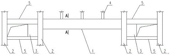
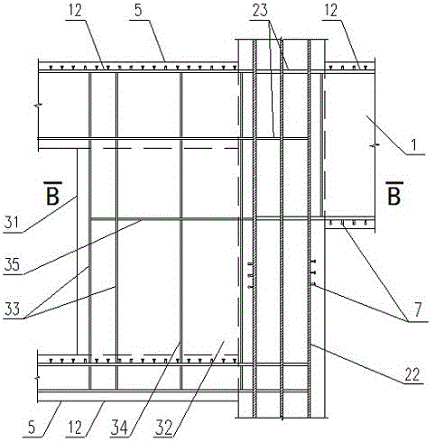
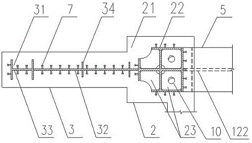
[0026] In the large-span structure of high-rise and super-high-rise buildings described in the present invention, a kind of adjacent span is provided with steel plate concrete shear wall beam supporting column conversion beam such as figure 1 As shown, there are steel concrete transfer beam 1, steel concrete column 2, steel plate concrete shear wall 3, square steel pipe concrete column 4 and steel concrete beam 5; described steel concrete conversion beam 1, steel concrete beam 5 are formed by Concrete beam 11, I-shaped steel beam 12, but its specific cross-sectional size and the spatial relationship of adjacent components are not the same; the steel concrete column 2 is composed of concrete column 21, cross-shaped steel frame 22, steel partition 23; The square steel pipe concrete column 4 is composed of a square steel pi...


PUM


Abstract

The invention relates to a column-supported-by-beam transfer beam with steel plate reinforced concrete shear walls arranged in adjacent spans. The column-supported-by-beam transfer beam comprises a profile steel reinforced concrete transfer beam body, profile steel reinforced concrete columns, the steel plate reinforced concrete shear walls, concrete-filled square steel tubular columns and profile steel reinforced concrete beams. The concrete-filled square steel tubular columns are arranged on the profile steel reinforced concrete transfer beam body. The steel plate reinforced concrete shear walls are located on the two sides of the profile steel reinforced concrete transfer beam body and symmetrically arranged at the whole layer height in the adjacent spans. The two sides of each profile steel reinforced concrete column are connected with the corresponding steel plate reinforced concrete shear wall and the profile steel reinforced concrete transfer beam body separately. The profile steel reinforced concrete columns and the steel plate reinforced concrete shear walls bear vertical loads and horizontal loads transferred by the profile steel reinforced concrete transfer beam body correspondingly. The steel plate reinforced concrete shear walls are arranged at the whole layer height in the adjacent spans to bear shear force, so that the problem that when the profile steel reinforced concrete transfer beam body is relatively high, the shear resistance of the profile steel reinforced concrete columns for supporting the profile steel reinforced concrete transfer beam body from the two sides may be insufficient is solved.

Description

technical field [0001] The invention relates to a transfer beam in the field of building structure engineering, in particular to a beam supporting column transfer beam with adjacent spans provided with steel plate concrete shear walls. Background technique [0002] At present, due to the different building functions of the upper and lower floors in high-rise and super high-rise buildings, there is a need to set transfer beams on certain floors to realize that some frame columns on the upper floors need to be canceled below a certain floor, so that the column span size of the bottom floor is larger than that of the upper floor. Department floor. Generally, when the total height of floors and the number of floors that need to be converted are small, the frame supports in the form of conventional "beam support columns" can meet the above-mentioned architectural functional requirements and properly solve such problems. [0003] For high-rise and ultra-high-rise buildings, the b...

Claims


Application Information

Patent Timeline
Patent Type & Authority Applications(China)
IPC IPC(8): E04B2/56E04C3/34E04C3/32E04C3/293
CPCE04B2/56E04C3/293E04C3/32E04C3/34
Inventor 张伟周晓光严力军陈龙夏熙尧
Owner 香港华艺设计顾问(深圳)有限公司
Why Eureka
Try Eureka