Rotating type concrete distribution device applied to sliding formwork

A distributing device and rotary technology, applied in the connection of formwork/formwork/work frame, construction material processing, formwork/formwork/work frame, etc., can solve the problem of filling, quality, Insufficient safety, concrete faults, etc., to ensure the quality of pouring, shorten the pouring time of concrete, and have strong structural stability.

Inactive Publication Date: 2017-03-22
CHINA FIRST METALLURGICAL GROUP
View PDF5 Cites 4 Cited by
  • Summary
  • Abstract
  • Description
  • Claims
  • Application Information

AI Technical Summary

Problems solved by technology

Slipform construction has been widely used in the concrete construction of the silo wall, and the concrete construction of the silo wall is the focus and difficulty of the entire construction process. When the slipform construction is used, the setting time of the silo wall concrete is not well controlled, and it is easy to cause Concrete faults affect the quality of the main structure of the silo
The traditional concrete pouring method is pumped to the slipform platform and then transported with a manual trolley. This method takes a long time to pour concrete, and the demand for masons is large, and it is easy to form interspersed operations with other types of work on the platform. Quality, safety no guarantee
[0003] During the slipform construction of the silo wall, the larger the diameter of the silo, the greater the demand for artificial trolleys, and the greater the impact of human factors on the pouring of trolleys, it is also easy to cause concrete faults. Vehicle walking and too many construction workers will affect the bearing capacity of the entire sliding form system, which in turn will affect the safety and stability of the sliding form system
Conventional silo wall concrete pouring methods cannot fill the lifting section of the sliding form in a short time
Existing technology can't solve above-mentioned problem better

Method used


Image

  • Rotating type concrete distribution device applied to sliding formwork
  • Rotating type concrete distribution device applied to sliding formwork
  • Rotating type concrete distribution device applied to sliding formwork

Examples


Embodiment Construction

[0017] In order to have a clearer understanding of the technical features, purposes and effects of the present invention, the specific implementation manners of the present invention will now be described in detail with reference to the accompanying drawings.

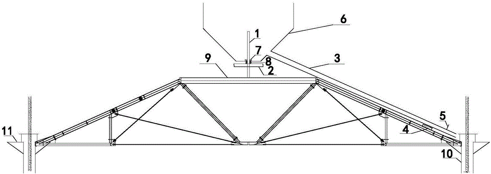
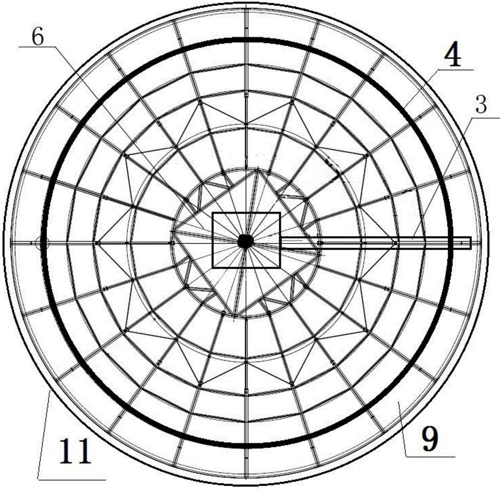
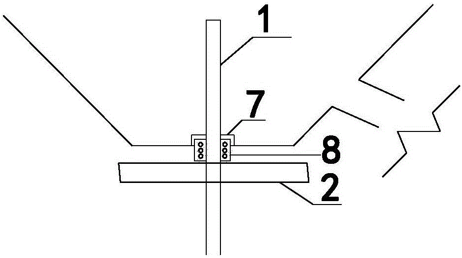
[0018] Such as Figure 1-Figure 3 As shown, the rotary concrete distributing device applied to the sliding form of the present invention includes an umbrella support platform 9, a column 1, a supporting plate 2, a chute 3, a track 4, a funnel 6 and a sliding form system 11.

[0019] The outer edge of the umbrella-shaped support platform 9 is provided with a sliding form system 11, and the middle part of the umbrella-shaped support platform 9 is provided with a column 1, which is in the shape of a circular tube. A support pallet 2 is fixedly arranged on the column 1, and a funnel 6 is arranged above the support pallet 2, and the funnel 6 can rotate around the column 1. The umbrella-shaped steel support is used as a load...


PUM


Abstract

The invention relates to a rotating type concrete distribution device applied to sliding formwork. The rotating type concrete distribution device comprises an umbrella supporting platform, wherein a sliding formwork system is arranged on the outer edge of the umbrella supporting platform, a stand column is arranged in the middle of the umbrella supporting platform, a bracing supporting plate is fixedly arranged on the stand column, a hopper is arranged above the bracing supporting plate and can rotate around the stand column, a leakage hole of the hopper is fixedly connected with a chute, a discharge outlet of the chute corresponds to a cabin wall to be poured, a circular track is arranged on the upper part of the umbrella supporting platform, and the chute can slide along with the track. The rotating type concrete distribution device can replace hand transportation and pouring, the concrete pouring quality can be guaranteed, the time of pouring the inner formwork of a hoisting section of the sliding formwork can be shortened.

Description

technical field [0001] The invention relates to the field of slip form construction, in particular to a rotary concrete distributing device applied to the slip form. Background technique [0002] In the construction of material storage projects such as grain and mineral powder, it is often encountered in the construction of large-scale silo cylindrical structures with conical roofs. Slipform construction has been widely used in the concrete construction of the silo wall, and the concrete construction of the silo wall is the focus and difficulty of the entire construction process. When the slipform construction is used, the setting time of the silo wall concrete is not well controlled, and it is easy to cause Concrete faults affect the quality of the main structure of the silo. The traditional concrete pouring method is pumped to the slipform platform and then transported with a manual trolley. This method takes a long time to pour concrete, and the demand for masons is larg...

Claims


Application Information

Patent Timeline
Patent Type & Authority Applications(China)
IPC IPC(8): E04H7/26E04G17/00E04G11/22E04G21/04
CPCE04H7/26E04G11/22E04G17/002E04G21/0481
Inventor 李永佳沈汉刚
Owner CHINA FIRST METALLURGICAL GROUP
Why Eureka
Try Eureka