Riser column group vibration anti-collision and power generation device and method

A power generation device, standpipe technology, applied in the direction of generator/motor, drill pipe, casing, etc.

Inactive Publication Date: 2017-03-22
SOUTHWEST PETROLEUM UNIV
View PDF7 Cites 9 Cited by
  • Summary
  • Abstract
  • Description
  • Claims
  • Application Information

AI Technical Summary

Problems solved by technology

[0005] The problem to be solved by the present invention is to provide a vibration anti-collision and power generation device for riser strings that effectively prevents the collision of the riser strings, fully utilizes the vibration energy, and has reliable performance in view of the collision phenomenon existing between the existing marine riser strings. method

Method used


Image

  • Riser column group vibration anti-collision and power generation device and method
  • Riser column group vibration anti-collision and power generation device and method
  • Riser column group vibration anti-collision and power generation device and method

Examples


Embodiment

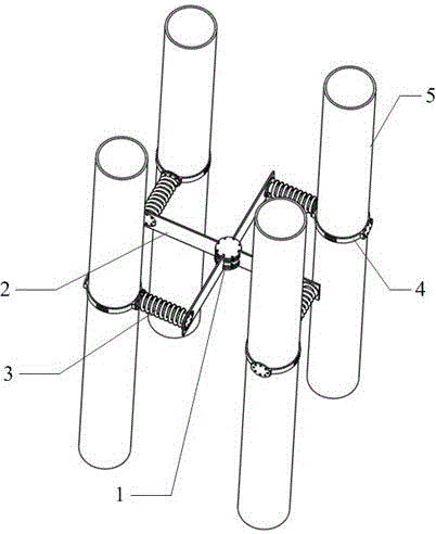
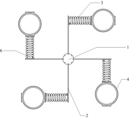
[0034] During actual installation, according to the number of 5 risers of the riser 5 column group and the relative position, choose to install them in an array or as a basic unit, and determine the number of 2 piezoelectric sheet integrated boards connected to a central steering wheel 1.

[0035] When installing a single basic unit, first set the fastening sleeve 4 on the outer wall of the riser 5, and then fix the fixed flange 9 at one end of the fastening sleeve 4 with the fixed flange 9 at one end of the nested telescopic tube 6 through bolt connection, The spring 3 is set outside the nested telescopic tube 6, and the fixed flange 9 at the other end of the nested telescopic tube 6 is engaged and fixed. Next, one end of the piezoelectric sheet integrated board 2 provided with the bolt holes required for connection with the fixed flange 9 is connected to the fixed flange 9 at the free end of the nested telescopic tube 6 through bolts, and the piezoelectric sheet integrated bo...


PUM


Abstract

The invention relates to a rotatable device and a method, and the device and the method can achieve piezoelectric power generation and vibration suppression synchronously. The device is composed of a rotation assembly, a piezoelectric assembly and a current guide assembly. The rotation assembly is responsible for achieving the rotation function of the whole device. Both the piezoelectric assembly and the current guide assembly are arranged in an asymmetrical mode. The piezoelectric assembly achieves power generation through deformation of piezoelectric patches. The current guide assembly generates torque needed by rotation through asymmetrical pore plates of different densities of pores. When seawater passes through cylindrical attached columns at the ends of the piezoelectric patches, the piezoelectric patches are induced to vibrate and deformed continuously, and a steady stream of currents is generated. A rotary current guide pate and the piezoelectric patches damage a streaming boundary layer on the surfaces of marine risers, formation of streaming vortexes is affected, and vibration suppression is achieved. By means of the marine risers, the device achieves piezoelectric power generation and vibration suppression synchronously.

Description

technical field [0001] The invention belongs to the technical field of laying of marine riser facilities, and in particular relates to a vibration anti-collision and power generation device and method for riser column groups. Background technique [0002] With the continuous increase of human demand for energy, the vigorous development of deep-water oil and gas resources and combustible ice has become an inevitable choice for human beings. The marine riser plays a vital role in the extraction and transportation of marine oil and gas and combustible ice. It connects the underwater wellhead or submarine pipeline on the seabed, and is responsible for lifting the production fluid to the offshore platform or floating platform on the water surface. The production device can be described as a bridge between the underwater and the water. Under the action of waves and currents, marine risers will undergo vortex-induced vibration, which is prone to fatigue damage. However, the comple...

Claims


Application Information

Patent Timeline
Patent Type & Authority Applications(China)
IPC IPC(8): E21B17/01E21B17/10H02N2/18
CPCE21B17/01E21B17/1035E21B17/1042H02N2/186
Inventor 朱红钧赵宏磊
Owner SOUTHWEST PETROLEUM UNIV
Why Eureka
Try Eureka