Subway tunnel air valve with high-temperature resistance, high strength, low leakage and low flow resistance
A high-strength, low-leakage technology, used in valve lift, heat preservation, valve details, etc., can solve problems such as not fully meeting requirements, and achieve the effect of improving rigidity and strength, reducing flow resistance coefficient, and improving sealing performance
- Summary
- Abstract
- Description
- Claims
- Application Information
AI Technical Summary
Problems solved by technology
Method used
Image

Examples
Embodiment 1
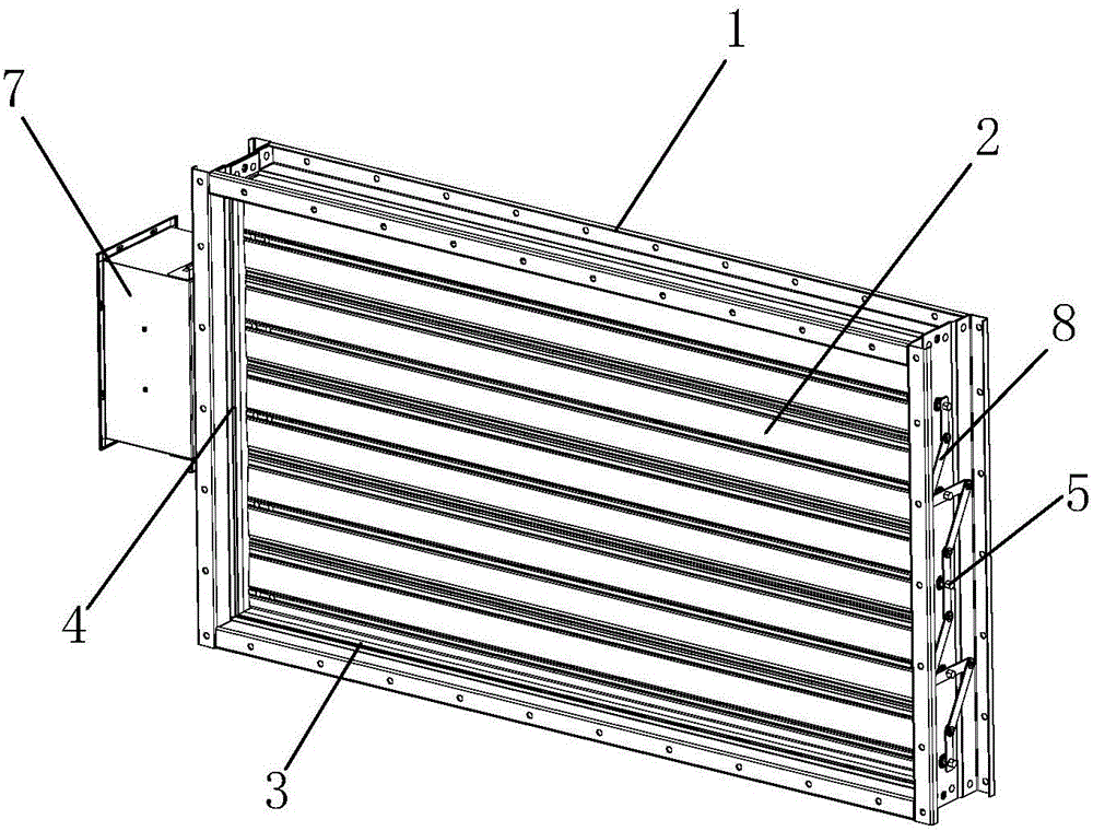
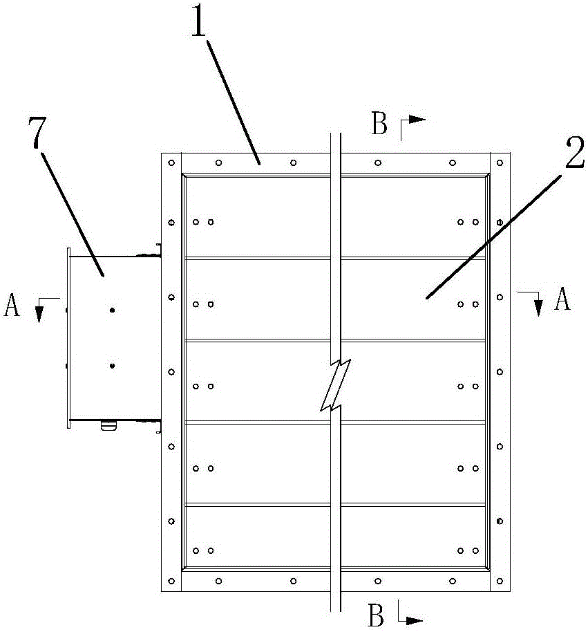
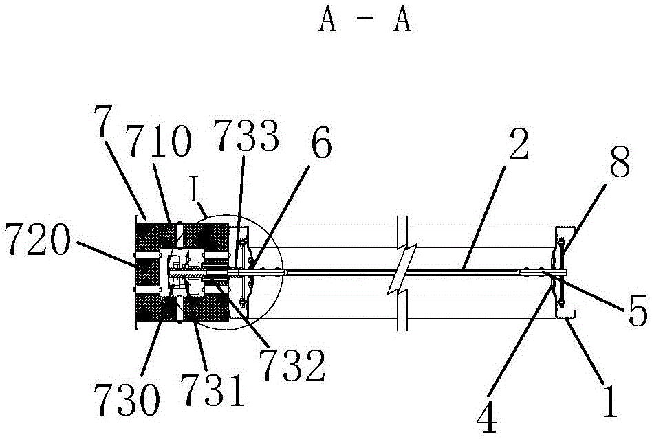
[0031] like Figures 1 to 7 As shown, a subway tunnel air valve with high temperature resistance, high strength, low leakage and low flow resistance includes valve body 1, blade 2A, valve seat 3A, sealing plate 4, rotating shaft 5, bearing 6, driving mechanism 7 and connecting Rod mechanism 8.
[0032] The frame section of the valve body 1 is "C" shaped and protrudes into the valve body 1. Both ends of the upper and lower frames of the valve body 1 are flanged upwards and connected with the two side frames by bolts. The valve seat 3A is located on the valve body. 1. On the inner wall of the upper and lower frames, the valve seat 3A is in the shape of an arch bridge and fits with the protrusions of the upper and lower frames.
[0033] The sealing sheet 4 is arranged on the inner wall of the frame on both sides of the valve body 1 , the sealing sheet 4 is in the shape of an arch bridge, and the sealing sheet 4 fits with the protrusions of the frames on both sides. Bearings 6 a...
Embodiment 2
[0037] The difference between the second embodiment and the first embodiment lies in the structure of the valve seat.
[0038] like Figure 9 middle Figure 9 As shown in .2, the valve seat 3B includes a baffle 310B and a pressing piece 320B. The baffle 310B is fixed on the protrusions of the upper and lower frames, and the pressing piece 320B is arranged on one side of the baffle 310B.
Embodiment 3
[0040] The difference between the third embodiment and the first embodiment lies in the structure of the blades.
[0041] like Figure 8 middle Figure 8 As shown in .2, the blade 2B includes two airfoils 210B with the same shape and a straight cross-section. The connecting plates 211B are arranged on both sides of the airfoil 210B. The blade 2B is symmetrically connected to the corresponding connecting plate 211B by bolts from the center of the airfoil 210B. or rivet connection, one side of the blade 2B is provided with a shrapnel 220B, and the side of the blade 2B with the shrapnel 220B is overlapped with the side of the other blade 2B without the shrapnel 220B between the two blades 2B, and the rotating shaft 5 passes through Bolts or rivets are installed between the two vanes 210B of the blade 2B.
PUM
 Abstract
Description
Claims
Application Information
 - R&D Engineer
- R&D Manager
- IP Professional
- Industry Leading Data Capabilities
- Powerful AI technology
- Patent DNA Extraction
Browse by: Latest US Patents, China's latest patents, Technical Efficacy Thesaurus, Application Domain, Technology Topic.
© 2024 PatSnap. All rights reserved.Legal|Privacy policy|Modern Slavery Act Transparency Statement|Sitemap