Fan turnover structure and temperature control equipment

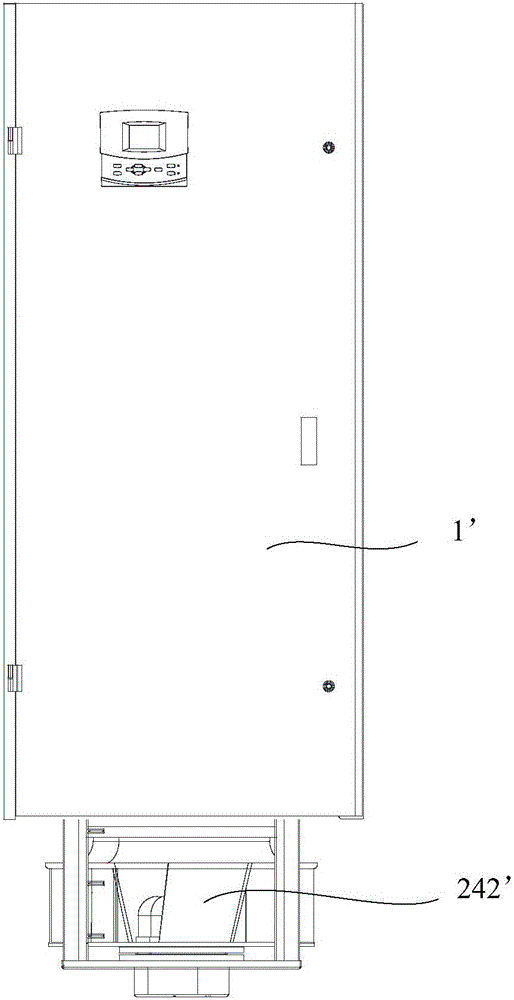
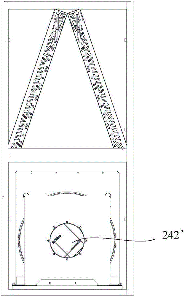
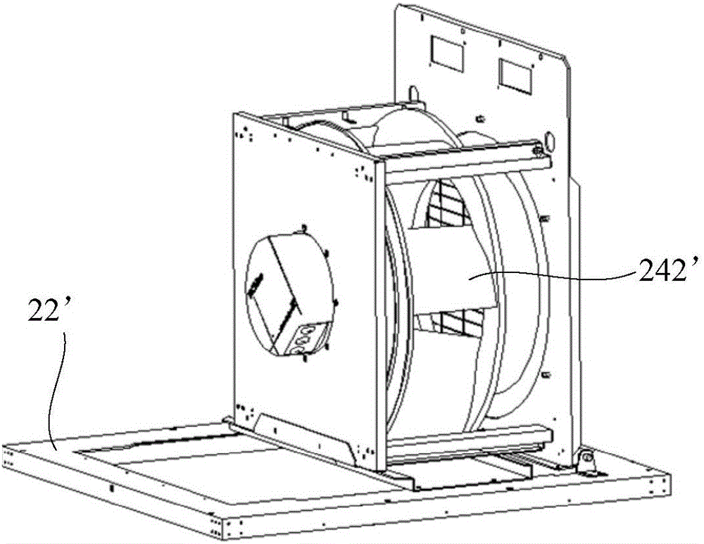
A technology of temperature adjustment equipment and flipping structure, which is applied in the field of air conditioning, and can solve problems such as the difficulty of turning down the fan 242', the heavy weight of the fan 242', and the increase of the overall height of the whole machine, so as to reduce labor intensity, facilitate operation, and reduce strength Effect

Pending Publication Date: 2017-03-22
GD MIDEA HEATING & VENTILATING EQUIP CO LTD +1
View PDF6 Cites 1 Cited by
  • Summary
  • Abstract
  • Description
  • Claims
  • Application Information

AI Technical Summary

Problems solved by technology

[0003] Because the fan 242' of this structure is located at the bottom of the cabinet 1', it brings great inconvenience to the packaging and transportation of the whole machine, and will increase the overall height of the whole machine. The general method is to put the fan 242' in the Inside the cabinet 1', turn the fan 242' from the inside

Method used


Image

  • Fan turnover structure and temperature control equipment
  • Fan turnover structure and temperature control equipment
  • Fan turnover structure and temperature control equipment

Examples


Example Embodiment

[0043] In order to be able to understand the above objectives, features and advantages of the present invention more clearly, the present invention will be further described in detail below in conjunction with the accompanying drawings and specific embodiments. It should be noted that the embodiments of the application and the features in the embodiments can be combined with each other if there is no conflict.

[0044] In the following description, many specific details are set forth in order to fully understand the present invention. However, the present invention can also be implemented in other ways different from those described here. Therefore, the protection scope of the present invention is not limited to the specific details disclosed below. Limitations of the embodiment.

[0045] Refer below Figure 4 with Figure 5 The fan turning structure 2 and the temperature adjusting device according to some embodiments of the present invention are described.

[0046] Such as Figure ...


PUM


Abstract

The invention provides a fan turnover structure and temperature control equipment. The temperature control equipment comprises a cabinet. The fan turnover structure is used for the temperature control equipment. The fan turnover structure comprises a cabinet base, a fan component and a turnover portion, wherein the cabinet base is located at the bottom of the cabinet and is in a slab shape, and a turnover opening is formed in the cabinet base; the fan component comprises a fan and a turnover plate, the fan is mounted on the turnover plate, and the turnover plate is located in the turnover opening and matched with the turnover opening; the turnover portion is arranged on the axis of symmetry of the cabinet base, and the turnover portion is connected with the cabinet base and the fan component; and the fan component turns over up and down around the axis of symmetry of the cabinet base. The fan turnover structure aims at reducing the strength of turning over the fan manually and lowering the risk of safety accidents, and especially for some space-narrow places, the beneficial effects of the structure can be further reflected.

Description

technical field [0001] The invention relates to the technical field of air conditioning, and in particular, relates to an overturning structure of a fan and a temperature regulating device. Background technique [0002] Centrifugal fans are often used as air supply components in air-conditioning units. Since the centrifugal fans are installed below the outside of the cabinet, they can effectively improve the air supply efficiency and improve the maintainability of the centrifugal fans. Therefore, they are widely used in the fan installation structure of air-conditioning units. In , the structural form of the whole machine usage status is as follows figure 1 . [0003] Because the fan 242' of this structure is located at the bottom of the cabinet 1', it brings great inconvenience to the packaging and transportation of the whole machine, and will increase the overall height of the whole machine. The general method is to put the fan 242' in the Inside the cabinet 1', turn the...

Claims


Application Information

Patent Timeline
IPC IPC(8): F24F1/00
CPCF24F1/0018F24F2221/36
Inventor 黎举辉
Owner GD MIDEA HEATING & VENTILATING EQUIP CO LTD
Why Eureka
Try Eureka