Heating furnace for conducting infrared flaring

A heating furnace and infrared technology, applied in electric furnace heating, lighting and heating equipment, furnaces, etc., can solve the problems of high production requirements and processing technology requirements, difficulty in meeting processing requirements, troublesome installation of pipe fittings, etc., to reduce labor intensity, Improve heat utilization and improve work efficiency

Active Publication Date: 2017-03-22
JIANGSU TIANBAO CERAMICS CO LTD
View PDF5 Cites 1 Cited by
  • Summary
  • Abstract
  • Description
  • Claims
  • Application Information

AI Technical Summary

Problems solved by technology

[0002] At present, pipe fittings are widely used in daily life, and the connection between pipe fittings usually adopts the socket method, so that the pipe fittings need to be narrower at one end and wider at the other end, so as to meet the socket installation, but in the pipe fittings production In the process, if the pipe fittings that meet the requirements are produced at one time, the production requirements and processing technology requirements are too high, while the production of pipe fittings with the same diameter is relatively simple, and a heating furnace is required for welding and forming of large pipes. Carry out heat treatment, but traditional firebox baking, using electric heating tape to wrap, not only consumes a lot of energy, the temperature is uneven, the installation of pipe fittings is troublesome and the heat conversion rate is low, it is difficult to meet the current processing requirements

Method used


Image

  • Heating furnace for conducting infrared flaring
  • Heating furnace for conducting infrared flaring
  • Heating furnace for conducting infrared flaring

Examples


Embodiment Construction

[0018] The following will clearly and completely describe the technical solutions in the embodiments of the present invention with reference to the accompanying drawings in the embodiments of the present invention. Obviously, the described embodiments are only some, not all, embodiments of the present invention. Based on the embodiments of the present invention, all other embodiments obtained by persons of ordinary skill in the art without making creative efforts belong to the protection scope of the present invention.

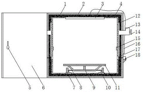
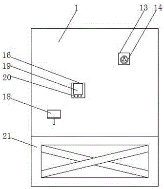
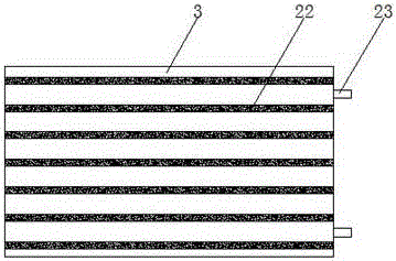
[0019] see Figure 1-4 , an embodiment provided by the present invention: an infrared flared heating furnace, comprising a furnace 1, a far-infrared ceramic radiator 3, a loading plate 11 and an air duct valve 13, the furnace 1 is provided with a refractory insulation layer 2, far The infrared ceramic radiator 3 is fixedly installed under the refractory insulation layer 2 at the inner top of the hearth 1, and the loading plate 11 is installed on the guide rail...


PUM


Abstract

The invention discloses a heating furnace for conducting infrared flaring. The heating furnace comprises a combustion chamber, a far infrared ceramic radiator, a carrying plate and an air duct valve. A fire-proof thermally-insulating layer is arranged inside the combustion chamber. Far infrared radiation coatings are uniformly applied to the inner surface of the fire-proof thermally-insulating layer and the inner surface of the far infrared ceramic radiator correspondingly. One end of a rotating shaft on a motor penetrates the combustion chamber and the fire-proof thermally-insulating layer and is fixedly connected with vanes in ventilation pipes. A temperature controller is electrically connected with the far infrared ceramic radiator and a temperature inductor through wires correspondingly. The far infrared ceramic radiator is formed by mounting a steel fixing plate, a thermally-insulating layer and a radiation plate in sequence from outside to inside. Copper binding posts are electrically connected with a heat-emitting resistance wire inside the radiation plate. Multiple rectangular protruding blocks are uniformly distributed on the surface of the radiation plate. According to the heating furnace for conducting infrared flaring, the far infrared ceramic radiator is adopted as a heat-emitting source, and the far infrared radiation coatings are added, so that the effects that temperature is raised fast and radiated uniformly, and the heat conversion rate is high are achieved.

Description

technical field [0001] The invention relates to the technical field of heating furnace equipment, in particular to an infrared flared heating furnace. Background technique [0002] At present, pipe fittings are widely used in daily life, and the connection between pipe fittings usually adopts the socket method, so that the pipe fittings need to be narrower at one end and wider at the other end, so as to meet the socket installation, but in the pipe fittings production In the process, if the pipe fittings that meet the requirements are produced at one time, the production requirements and processing technology requirements are too high, while the production of pipe fittings with the same diameter is relatively simple, and a heating furnace is required for welding and forming of large pipes. Heat treatment is carried out, but the traditional firebox baking is wrapped with electric heating belt, which not only consumes a lot of energy, but also has uneven temperature, troubleso...

Claims


Application Information

Patent Timeline
Patent Type & Authority Applications(China)
IPC IPC(8): F27B17/00F27D11/02F27D19/00F27D21/00
Inventor 柯安华周小波
Owner JIANGSU TIANBAO CERAMICS CO LTD
Why Eureka
Try Eureka