
Field vibration load identification-based evaluation method and system

A vibration load and on-site technology, which is applied to measuring devices, instruments, and measuring ultrasonic/sonic/infrasonic waves, etc., can solve the problems of cumbersome testing process, easy interference of result accuracy, failure to obtain vibration spectrum, etc., and achieve low testing risk , easy operation and high precision

Active Publication Date: 2017-03-22
ZHUZHOU CSR TIMES ELECTRIC CO LTD
View PDF7 Cites 20 Cited by
  • Summary
  • Abstract
  • Description
  • Claims
  • Application Information

AI Technical Summary

Problems solved by technology

These methods have several deficiencies: First, due to the limitations of on-site test safety, measuring point layout space, and the number of measuring points, only a limited number of measuring point vibration data can be measured, and vibration spectra of all parts and sub-components cannot be obtained; Second, the stress test and calibration method to obtain the force load test process is relatively cumbersome, and the accuracy of the results is easily disturbed

Method used


Image

  • Field vibration load identification-based evaluation method and system
  • Field vibration load identification-based evaluation method and system
  • Field vibration load identification-based evaluation method and system

Examples


Embodiment 1

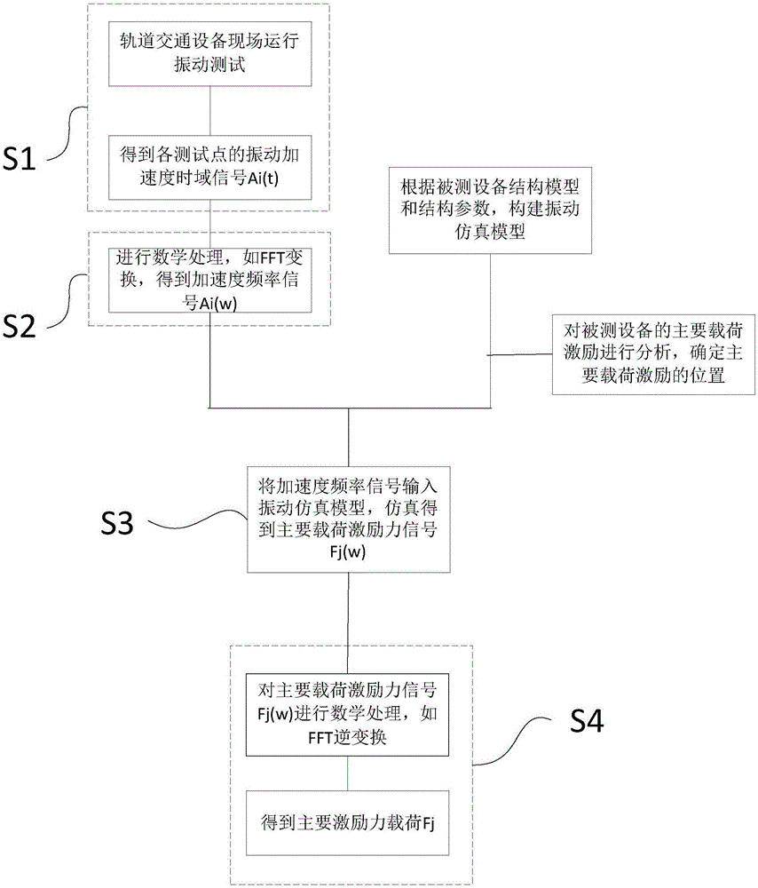
[0061] Such as figure 1 As shown, the evaluation method based on on-site vibration load identification of this embodiment includes: S1. Obtaining the vibration acceleration time-domain data of the equipment under test in actual operation through the method of on-site testing; S2. The vibration acceleration time-domain data Perform mathematical processing to calculate the vibration acceleration frequency data; S3. According to the pre-designed vibration simulation model of the device under test and the predetermined main load excitation force position of the device under test, input the acceleration frequency data into the The vibration simulation model is used to calculate the main load excitation force of the device under test; S4. Mathematically process the main load excitation force to obtain the main excitation force load of the device under test.

[0062] In this embodiment, the specific steps of step S1 include: arranging sensors at pre-selected measuring point positions...

Embodiment 2

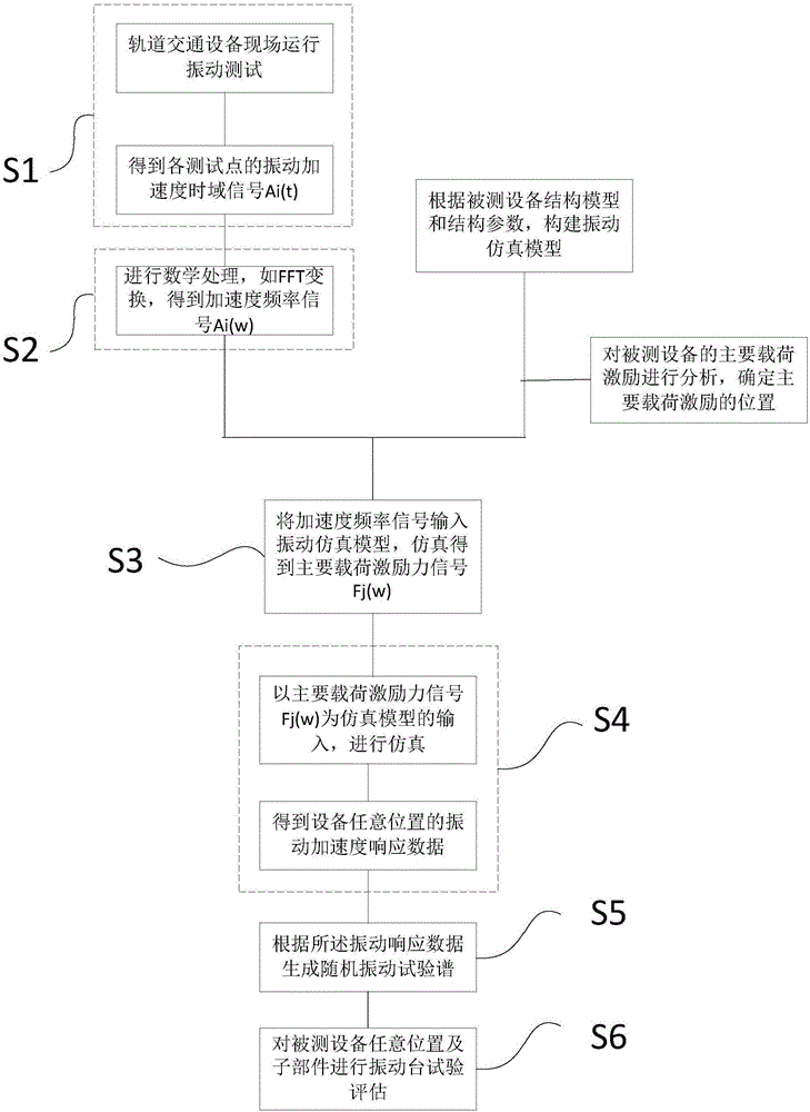
[0070] Such as figure 2 As shown, the steps S1, S2 and S3 of the evaluation method based on on-site vibration load identification in this embodiment are the same as the steps S1, S2 and S3 in the first embodiment, except for steps S4, S5 and S6. In this embodiment, S4. Input the excitation force of the main load into the vibration simulation model, and calculate the vibration response data of any position and sub-components of the device under test through simulation. S5. Generate a random vibration test spectrum according to the vibration response data; S6. Perform a shaking table test evaluation on any position and sub-components of the device under test according to the random vibration test spectrum.

[0071] In this embodiment, the main load excitation force F obtained in step S3 is j (ω),j=1,2,...,N are input to the vibration simulation model, and the vibration response data of any position of the device under test and any sub-component can be determined through simula...

Embodiment 3

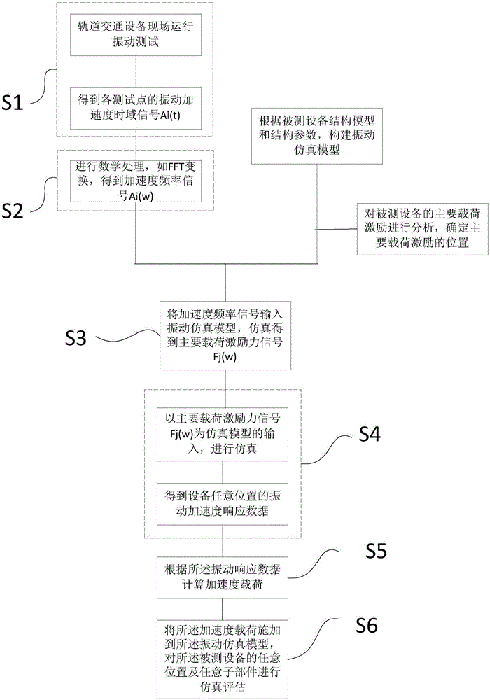
[0074] Such as image 3 As shown, steps S1, S2, S3 and S4 of the assessment method based on on-site vibration load identification in this embodiment are the same as steps S1, S2, S3 and S4 in the second embodiment, except for steps S5 and S6. In this embodiment, after the step S4, steps S5 and S6 are also included: S5. Calculate the acceleration load according to the vibration response data; S6. Apply the acceleration load to the vibration simulation model, and apply the acceleration load to the vibration simulation model. Any position and any sub-component of the test equipment can be simulated and evaluated. In this embodiment, the method of calculating the acceleration load based on the vibration response data in step S5 is to select a conventional processing method to organize the vibration response data into acceleration loads according to the type of simulation evaluation selected in step S6. The simulation evaluation in step S6 includes static strength simulation evalu...


PUM


Abstract

The invention discloses a field vibration load identification-based evaluation method and a system. The method comprises the steps of S1, obtaining the vibration acceleration time-domain data of to-be-tested equipment during the actual operation through the field test method; S2, subjecting the vibration acceleration time-domain data to mathematical treatment and obtaining the vibration acceleration frequency data of the equipment through calculating; S3, according to a pre-designed vibration simulation model of the to-be-tested equipment and a pre-determined main load exciting-force position of the to-be-tested equipment, inputting the vibration acceleration frequency data into the vibration simulation model, and obtaining the main load exciting force of the to-be-tested equipment through calculating; S4, subjecting the main load exciting force to mathematical treatment and obtaining the main exciting force load of the to-be-tested equipment through calculating. According to the technical scheme of the invention, based on the field vibration test and the simulated calculation, the actual vibration and force load environment for all parts and the sub-components of the equipment can be obtained according to limited and actually measured vibration data. The method and the system have the advantages of convenient operation, low testing risk, high evaluation accuracy and the like.

Description

technical field [0001] The invention relates to the technical field of rail transit vibration test evaluation, in particular to an evaluation method and system for rail traffic vibration tests based on on-site vibration load identification. Background technique [0002] Modern rail transit equipment generally needs to be evaluated by shock and vibration tests. Standards such as GB / T21563 (or IEC61373) are usually used for evaluation. However, this standard is different from the vibration environment of equipment test operation, and cannot simulate the real bearing situation. Therefore, equipment manufacturers generally obtain actual operating vibration data through on-site testing, and then form a vibration load spectrum; in addition, they also use stress testing and calibration methods to obtain force loads at locations such as bogies. These methods have several deficiencies: First, due to the limitations of on-site test safety, measuring point layout space, and the number ...

Claims


Application Information

Patent Timeline
Patent Type & Authority Applications(China)
IPC IPC(8): G01H17/00
CPCG01H17/00
Inventor 王永胜臧晓斌丁杰刘敏班立权饶沛南李振鹏魏周艳武宗祥
Owner ZHUZHOU CSR TIMES ELECTRIC CO LTD
Learn More