Rotary prism device driven by non-circular gears

A non-circular gear and rotating prism technology, applied in the field of precision optical scanning, can solve the problems of difficult cam profile curve design and processing, inability to drive the full circle rotation of the prism, affecting the deflection accuracy of the prism, etc., to ensure high-precision dynamic scanning. performance, reduced control requirements, and accurate transmission

Inactive Publication Date: 2018-12-04
TONGJI UNIV
View PDF4 Cites 0 Cited by
  • Summary
  • Abstract
  • Description
  • Claims
  • Application Information

AI Technical Summary

Problems solved by technology

However, the scope of application of this invention is limited to the deflection prism, and the prism cannot be driven to achieve full circle rotation; and the design and processing of the cam profile curve is relatively difficult, and its error will directly affect the deflection accuracy of the prism

Method used


Image

  • Rotary prism device driven by non-circular gears
  • Rotary prism device driven by non-circular gears
  • Rotary prism device driven by non-circular gears

Examples


Embodiment 1

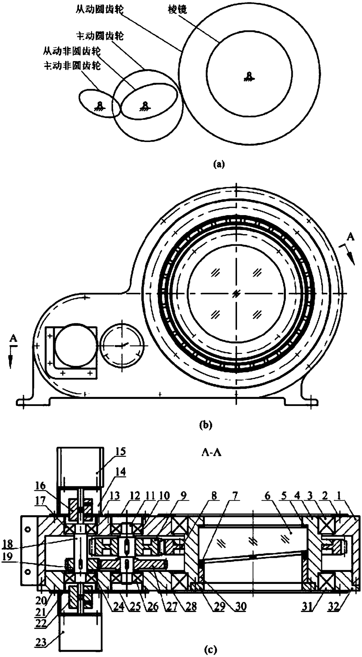
[0039] In this embodiment, two devices of the present invention are used, and the two prisms are arranged coaxially during installation to form a rotating double prism system. Below in conjunction with the accompanying drawings, taking a device of the present invention as an example, the structural principle and working process of the device of the present invention will be described in detail.

[0040] see figure 1 , in the rotating prism device, the rotating motor 15 drives a two-stage reduction system consisting of a pair of non-circular gears and a pair of cylindrical gears, and transmits the nonlinear motion relationship to the driven circular gear. The prism is rigidly coupled with the mirror frame assembly and the driven circular gear 8, therefore, the present invention can realize the precise rotational movement of the wedge-shaped prism 6 within the full circumference range.

[0041] see figure 1 , the prism and frame assembly includes a frame 4 , a prism washer 5 ,...


PUM


Abstract

The invention relates to a rotating prism device under non-circular gear driving. The rotating prism device comprises a prism and frame assembly, a drive system and a base assembly. The prism and frame assembly consists of a frame, s prism washer, a wedged prism, a rubber cushion block, a prism retainer ring and a wedged retainer ring. The drive system includes a rotary motor, a rotary encoder, a motor bearing seat, a rotary encoder support seat, a coupling unit, a driving shaft, a driven shaft, an active non-circular gear, a driven non-circular gear, an active circular gear and a driven circular gear. The base assembly includes a base, a bearing retainer ring, a bearing end cover, a base insert unit, a rolling bearing. The shapes of the non-circular gears are designed based on a non-linear relationship between the rotation angle of the wedged prism and a deflection angle of an emergent light beam. A drive motor only needs to rotate at a constant speed to realize high-precision beam scanning at a specific track, so that the requirement on control of the rotating prism system is reduced. Besides, the rotary encoder is arranged inside the drive system and is used for detecting the practical rotation angle of the driving shaft in real time; a computer processes the collected data; and an opened-loop way or a closed-loop way is employed flexibly according to practical needs, so that the proper prism rotation precision is obtained.

Description

technical field [0001] The invention relates to an optical scanning device, in particular to a rotating prism device driven by a non-circular gear, and belongs to the field of precision optical scanning. Background technique [0002] In the field of precision optical scanning, the rotating prism device has a wide range of uses, and can accurately realize the scanning of the target area, the tracking of the measured object, the alignment of the optical path, and the compensation and correction of the beam pointing error. However, there is usually a complex nonlinear relationship between the rotation angle of the rotating prism and the deflection angle of the scanning beam, which brings difficulties to the motion control of the rotating prism. Precisely controlling the rotational movement of the prism and ensuring the real-time performance of dynamically adjusting the prism angle are the key to improving the performance of the rotating prism system. [0003] The following pri...

Claims


Application Information

Patent Timeline
Patent Type & Authority Patents(China)
IPC IPC(8): G02B26/10
CPCG02B26/108
Inventor 李安虎刘兴盛易万力
Owner TONGJI UNIV
Why Eureka
Try Eureka