
Shaft hoisting container charging device

A charging device and wellbore technology, applied in the direction of circuit devices, battery circuit devices, collectors, etc., can solve the problems of small battery capacity, restrictions on automatic loading, difficult maintenance, etc., to prevent electrification, prevent creepage, and improve safety Effect

Pending Publication Date: 2017-03-22
苏士清
View PDF0 Cites 0 Cited by
  • Summary
  • Abstract
  • Description
  • Claims
  • Application Information

AI Technical Summary

Problems solved by technology

[0002] With the improvement of coal mine production automation, many shaft automation projects have been applied, but the automation projects need power as power. Since the vertical shaft hoisting container moves up and down in the shaft by winding the hoisting wire rope on the winch drum, it is difficult to provide power for the hoisting container. , often use batteries, and the battery capacity is small, and it needs to be replaced after only 7 to 15 days of use. It is difficult to maintain in the long run. Therefore, the power supply of the shaft lifting container seriously restricts the automatic loading of the shaft lifting container and the online monitoring of the container operation. , Wellbore equipment automatic measurement, wellbore train signal transmission and reception, wellbore video and intercom and other system project development

Method used


Image

  • Shaft hoisting container charging device
  • Shaft hoisting container charging device
  • Shaft hoisting container charging device

Examples


Embodiment Construction

[0014] The present invention will be further elaborated below in conjunction with the accompanying drawings and specific embodiments.

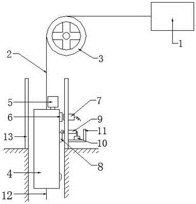
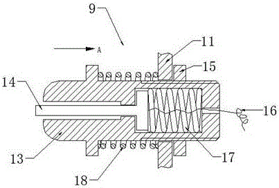
[0015] A shaft hoist container charging device, including a motor 1, a traction rope 2, a drum 3, a shaft hoist container 4, a lithium battery 5, a magnetic source 6, a position sensor 7, a buffer contact (8), a contact charger 9, and an explosion-proof power supply Box 10, fixed bracket 11 and balance tail rope 12, the traction rope 2 bypasses the drum 3, one end is connected with the motor 1, and the other end is connected with the wellbore lifting container 4, and the motor 1 lifts the wellbore container 4 through the traction rope 2 , the lithium battery 5 is installed on the top of the shaft lifting container 4, the magnetic source 6 is installed on the outer wall of the shaft lifting container 4, and is close to the top, the position sensor 7 is installed on the inner wall of the shaft, and the position sensor 7 Aligned on a line with th...


PUM


Abstract

The invention relates to a shaft hoisting container charging device, which comprises a motor, a pulling rope, a roller, a shaft hoisting container, a lithium battery, a magnetic source, a position sensor, a buffer contact, a contact charger, an explosion-proof power box, a fixed bracket and a balance tail rope, wherein one end of the pulling rope is connected with the motor and the other end is connected with the shaft hoisting container; the motor lifts the shaft hoisting container through the pulling rope; the lithium battery is arranged at the top of the shaft hoisting container; the magnetic source is arranged on the outer wall of the shaft hoisting container; the position sensor is arranged on the inner wall of a shaft; the buffer contact is arranged at one side of the outer wall of the shaft hoisting container; the contact charger is arranged at the bottom of the position sensor; the explosion-proof power box is connected with the contact charger; the explosion-proof power box is arranged on the wall of the shaft through the fixed bracket; and the tail rope is arranged at the bottom of the shaft hoisting container. The shaft hoisting container charging device is safe, reliable and suitable for popularization and application.

Description

technical field [0001] The invention relates to the field of mine electromechanical automation control, in particular to a charging device for a shaft hoisting container. Background technique [0002] With the improvement of coal mine production automation, many shaft automation projects have been applied, but the automation projects need power as power. Since the vertical shaft hoisting container moves up and down in the shaft by winding the hoisting wire rope on the winch drum, it is difficult to provide power for the hoisting container. , often use batteries, and the battery capacity is small, and it needs to be replaced after only 7 to 15 days of use. It is difficult to maintain in the long run. Therefore, the power supply of the shaft lifting container seriously restricts the automatic loading of the shaft lifting container and the online monitoring of the container operation. , The development of system projects such as automatic measurement of wellbore equipment, tran...

Claims


Application Information

Patent Timeline
Patent Type & Authority Applications(China)
IPC IPC(8): H02J7/02
CPCH02J7/027
Inventor 王巍赵强高月奎房兆光秦岩万召田孙磊徐涛涛侯成安李哲
Owner 苏士清
Learn More