A charging control method and device

A charging control and charging control chip technology, applied in circuit devices, battery circuit devices, current collectors, etc., can solve problems affecting user experience and high terminal temperature, and achieve the effects of improving user experience, temperature control, and speed.

Active Publication Date: 2018-12-28
MEIZU TECH CO LTD
View PDF3 Cites 0 Cited by
  • Summary
  • Abstract
  • Description
  • Claims
  • Application Information

AI Technical Summary

Problems solved by technology

[0005] Embodiments of the present invention provide a charging control method and device to solve the problem in the prior art that the temperature of the terminal is too high due to charging and affects the user experience

Method used


Image

  • A charging control method and device
  • A charging control method and device
  • A charging control method and device

Examples


Embodiment 1

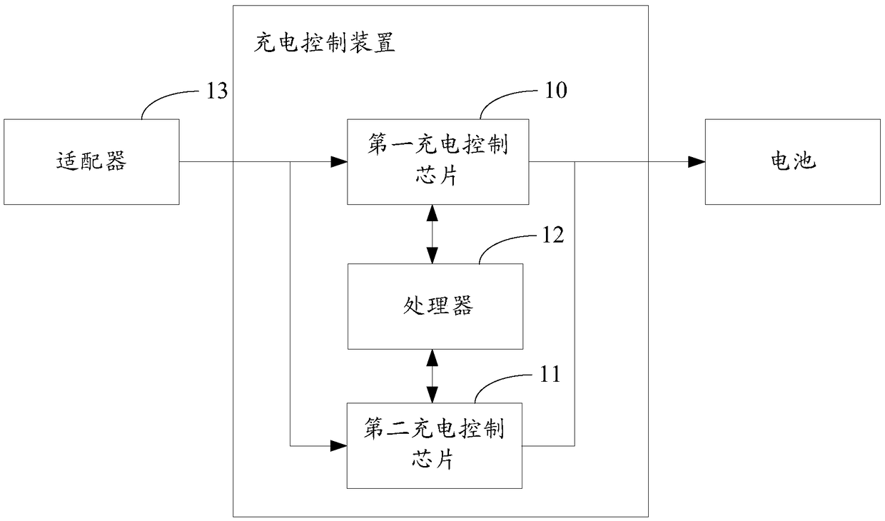
[0055] Refer to figure 1 As shown, in the embodiment of the present invention, the charging control device includes two charging control chips, an adapter, and a processor. Among them,

[0056] The first charging control chip 10 is respectively connected to the output terminal of the adapter 13 and the input terminal of the battery;

[0057] The second charging control chip 11 is respectively connected to the output terminal of the adapter 13 and the input terminal of the battery; wherein the second charging control chip 11 and the first charging control chip 10 are connected in parallel;

[0058] The processor 12 is respectively connected to the first charging control chip 10 and the second charging control chip 11, and is used to obtain the voltage and temperature of the battery, the temperature of the first charging control chip 10 and the second charging control chip 11 respectively, and according to all The voltage and temperature of the battery, the temperature of the first cha...

Embodiment 2

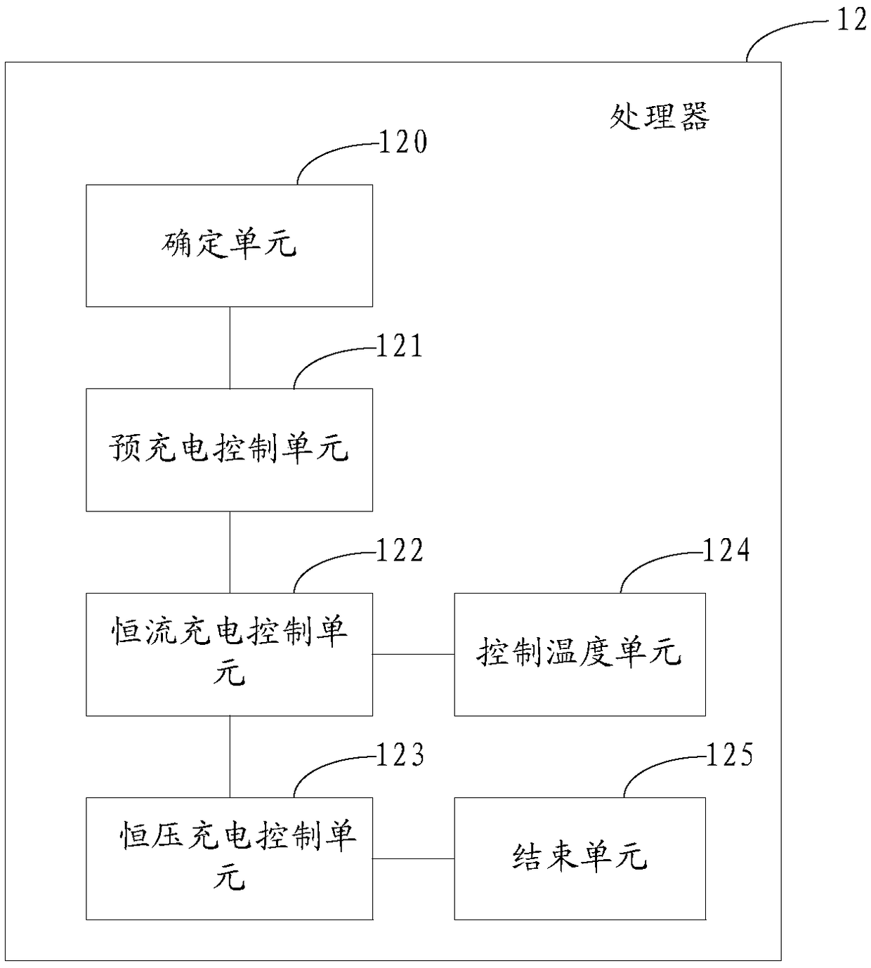
[0068] Refer to figure 2 As shown, based on the detailed description of the first embodiment, the processor 12 may control the first charging control chip 10 and the second charging control chip 11 to charge the battery based on various voltage and temperature information acquired. . Specifically, the processor 12 includes:

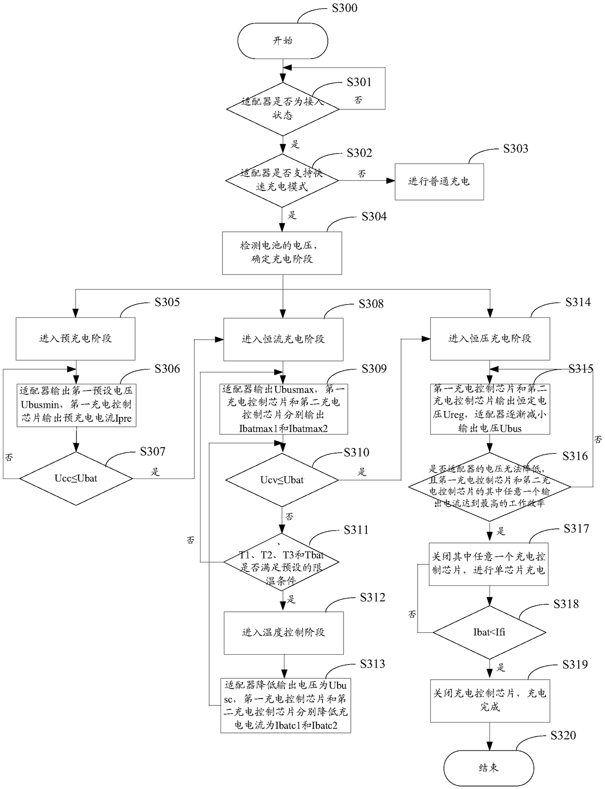
[0069] The pre-charging control unit 121 is used to determine that when the voltage of the battery is not less than a first preset threshold and less than a second preset threshold, control the second charging control chip 11 to not work and the first charging control chip 10 to enter the pre-charging stage, and The first charging control chip is controlled to charge the battery with a preset pre-charging current, and the adapter 13 is controlled to output a first preset voltage.

[0070] The first preset voltage is the minimum voltage of the adapter 13.

[0071] For example, if the battery voltage is Ubat, the first preset threshold is Upre, the second prese...

Embodiment 3

[0080] Refer to figure 2 As shown, on the basis of the above embodiment, in the constant current charging stage, the embodiment of the present invention no longer always charges the battery with the maximum current that the battery can withstand. Instead, the temperature control unit 124 is added to enable charging The control chip switches between high-power and high-efficiency states to control the temperature of the terminal.

[0081] In the constant current charging stage, the processor 12 further includes a temperature control unit 124, configured to:

[0082] In the constant current charging stage, the first temperature of the first charging control chip 10, the second temperature of the second charging control chip 11, the third temperature of the main board, and the fourth temperature of the battery are obtained respectively;

[0083] When it is determined that the first temperature, the second temperature, the third temperature, and the fourth temperature meet the preset te...


PUM


Abstract

The invention relates to the technical field of charging, and particularly relates to a charging control method and device. The charging control device comprises two charging control chips, an adapter and a processor, wherein the first charging control chip and the second charging control chip are connected in parallel, and the processor respectively acquires the voltage and the temperature of a battery, the temperature of the first charging control chip and the temperature of the second charging control chip, and controls the first charging control chip and the second charging control chip to charge the battery according to the voltage and the temperature of the battery, the temperature of the first charging control chip and the temperature of the second charging control chip. Therefore, charging for the battery is controlled according to the detected temperature and the detected voltage, a problem that the temperature of a terminal is caused to be too high by charging in the prior art, and the user experience in use is improved. The embodiment of the invention is applicable to quick charging equipment for a terminal battery, quick charging can be performed on the terminal battery, and the charging control device has the advantages of high power, high speed and controllable temperature.

Description

Technical field [0001] The present invention relates to the field of charging technology, in particular to a charging control method and device. Background technique [0002] At present, the application of terminals is becoming more and more extensive, enhancing the user's ability to obtain information, and realizing that users can use the terminal to handle various affairs anytime and anywhere, which has become an indispensable part of life. In addition, the data transmission rate of the terminal and the processing rate of the chip are greatly improved, and accordingly, the power consumption of the terminal will also increase. Therefore, in order to ensure the endurance of the terminal, the fast charging technology of the terminal has become a research hotspot. [0003] In the prior art, the fast charging method usually uses a charging device in which two charging control chips are connected in parallel for charging. [0004] However, in the fast charging method in the prior art, d...

Claims


Application Information

Patent Timeline
Patent Type & Authority Patents(China)
IPC IPC(8): H02J7/04
CPCH02J7/007192H02J7/045
Inventor 王韡杨俊
Owner MEIZU TECH CO LTD
Why Eureka
Try Eureka