Efficient isolation type DC full-bridge conversion circuit

A full-bridge conversion and full-bridge circuit technology, which is applied in the field of high-efficiency isolated DC full-bridge conversion circuits, can solve the problems of large current, large on-state loss of the main circuit, and large additional on-state loss of the switching device of the lagging bridge arm. Achieve the effect of current reduction and additional on-state loss reduction

Inactive Publication Date: 2017-03-22
TIANJIN UNIV
View PDF9 Cites 3 Cited by
  • Summary
  • Abstract
  • Description
  • Claims
  • Application Information

AI Technical Summary

Problems solved by technology

[0005] 1. If the current of the switching device of the lagging arm is enhanced to ensure the realization of zero-voltage switching, when the auxiliary current source part uses a voltage equalizing capacitor, the additional on-state loss of the switching device of the lagging arm is relatively large
[0006] 2. The turn ratio of the primary side to the secondary side of the auxiliary transformer T1 is 1:1. When an additional current is injected into the lagging bridge arm, it will cause a large additional on-state loss of the switching device of the leading bridge arm, and at the same time, it will cause the input power to inject this Auxiliary current source section with larger current
[0007] 3. When the circuit is in the 0 working state, the high-frequency transformer includes certain copper loss and iron loss, the rectifier diodes D1 and D2, the filter inductor L and the filter capacitor C all have certain losses, and the overall on-state loss of the main circuit is relatively large

Method used


Image

  • Efficient isolation type DC full-bridge conversion circuit
  • Efficient isolation type DC full-bridge conversion circuit
  • Efficient isolation type DC full-bridge conversion circuit

Examples


Embodiment Construction

[0026] The following describes the embodiments of the present invention in further detail with reference to the accompanying drawings:

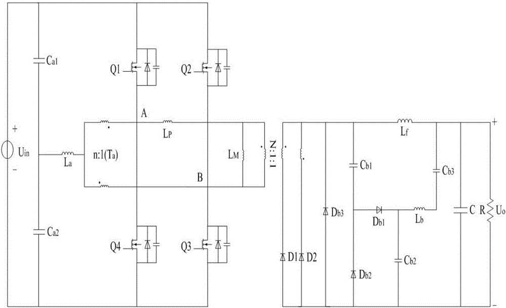
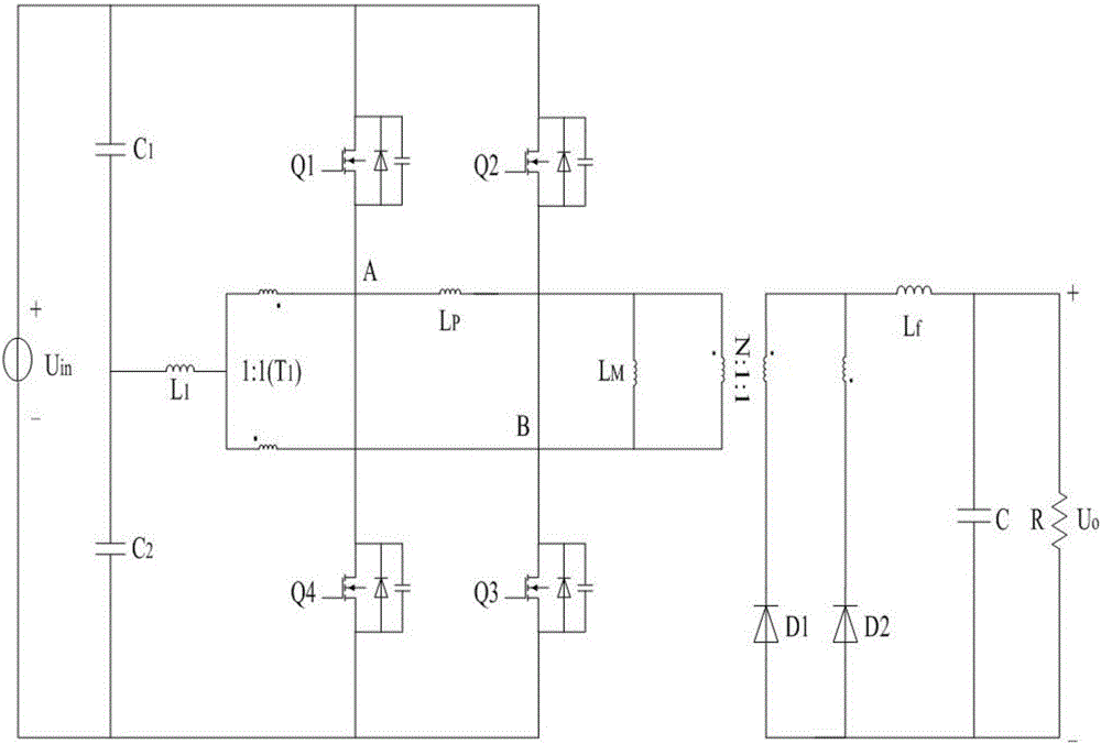
[0027] A high-efficiency isolated DC full-bridge conversion circuit is a comparison of existing isolated DC full-bridge conversion circuits (such as image 3 Shown) is improved. The high-efficiency isolated DC full-bridge conversion circuit is composed of six parts: auxiliary current source, full-bridge circuit, high-frequency transformer, synchronous rectifier circuit, filter circuit and reset capacitor circuit. It is the same as the existing isolated DC full-bridge conversion circuit ( image 3 ) Has the following differences:

[0028] 1. C in the existing conversion circuit 1 And C 2 It is a voltage equalizing capacitor, the midpoint voltage of the two remains unchanged, and the magnitude is the input voltage U in Half of it. Although the conversion circuit of the present invention still connects the two capacitors in series in the auxiliary cur...


PUM


Abstract

The invention relates to an efficient isolation type DC full-bridge conversion circuit comprising an auxiliary current source, a full-bridge circuit, a high-frequency transformer, a synchronous rectification circuit and a filter circuit. The input end of the auxiliary current source is connected in parallel with an input power supply, and the output end is connected with the midpoints of the two bridge arms of the full-bridge circuit. The primary side of the high-frequency transformer is connected with the midpoints of the two bridge arms of the full-bridge circuit, the non-common end of the secondary side is connected with the synchronous rectification circuit, and the common end of the secondary side is connected with the filter circuit. The technical characteristics are that the common end of the secondary side of the high-frequency transformer is also connected with a reset capacitive circuit, and the output ends of the reset capacitive circuit and the filter circuit are connected in parallel with a load together. The reset capacitive auxiliary circuit is arranged at the secondary side of the high-frequency transformer, and the auxiliary circuit is mainly used for realizing the reset function of the current of the two sides of the high-frequency transformer so that the power transmission efficiency can be enhanced to some extent, and the circuit can be applied to the electrical conversion device of new energy power generation and electric automobiles.

Description

Technical field [0001] The invention belongs to the technical field of automotive switching power supplies, in particular to a high-efficiency isolated DC full-bridge conversion circuit. Background technique [0002] At present, isolated DC full-bridge conversion circuits have been widely used in various fields, such as new energy power generation, server power supply, electric vehicles, etc. As the working environment of the conversion circuit is becoming more and more complex, as a power conversion and transmission device, power transmission efficiency has become an important topic of concern. In order to improve the power transmission efficiency of the isolated DC full-bridge conversion circuit, many scholars have added or improved different forms of auxiliary circuits on the basis of the typical conversion circuit. The functions of these auxiliary circuits can be roughly divided into two categories: enhancing the soft switching capability of the full-bridge circuit; reducing...

Claims


Application Information

Patent Timeline
Patent Type & Authority Applications(China)
IPC IPC(8): H02M3/335
CPCH02M3/33523H02M3/33592H02M1/0058Y02B70/10
Inventor 李冬辉姚乐乐贾冠龙闫振林刘玲玲
Owner TIANJIN UNIV
Why Eureka
Try Eureka